Conformal, Lightweight, Aerogel-Based Antenna
Communications
Conformal, Lightweight, Aerogel-Based Antenna (LEW-TOPS-155)
A Flexible Antenna for Active Aeronautical Satellite Communications
Overview
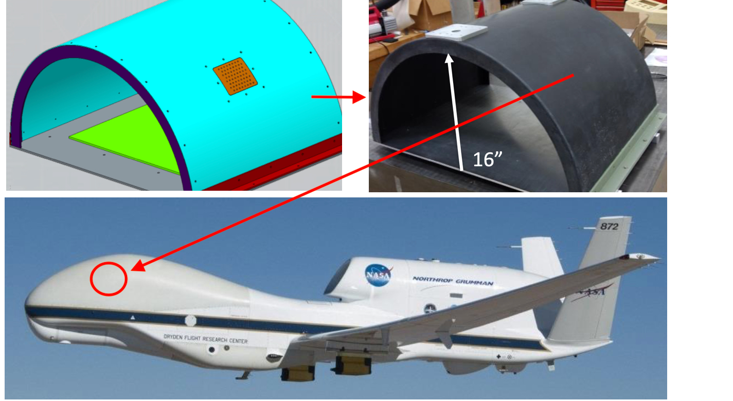
Innovators at the NASA Glenn Research Center have developed the Conformal, Lightweight Antenna for Aeronautical Communications Technology (CLAS-ACT), an active phased array antenna for Ku-band satellite communications on a mobile platform such as a UAV. The CLAS-ACT was developed for UAVs that require operations outside of radio line of sight which use a satellite link to increase operational coverage for command and control. The satellites typically used for this application fly a geostationary orbit at a very high altitude. The current state of practice for UAVs travelling out of line of sight is to use a large parabolic dish antenna that is pointed with a mechanical gimbal; this requires a significant volume within the UAV, adds unnecessary weight, and demands a large amount power. NASA's CLAS-ACT antenna improves upon current practice by offering a lightweight, small-sized antenna that can be mounted on the curved frame of an aircraft and has advanced beam steering/beam synthesis capabilities, enabling the efficient command and control of small or large UAVs used for a variety of purposes.
The Technology
This CLAS-ACT is a lightweight, active phased array conformal antenna comprised of a thin multilayer microwave printed circuit board built on a flexible aerogel substrate using new methods of bonding. The aerogel substrate enables the antenna to be fitted onto curved surface. NASA's prototype operates at 11-15 GHz (Ku-band), but the design could be scaled to operate in the Ka-band (26 to 40 GHz).
The antenna element design incorporates a dual stacked patch for wide bandwidth to operate on both the uplink and downlink frequencies with a common aperture. These elements are supported by a flexible variant of aerogel that allows the material to be thick in comparison to the wavelength of the signal with little to no additional weight. The conformal antenna offers advantages of better aerodynamics for the airframe, and potentially offers more physical area to either broadcast further distances or to broadcast at a higher data rate. The intended application for this antenna is for UAVs that need more than line of sight communications for command and control but cannot accommodate a large satellite dish. Examples may be UAVs intended for coastal monitoring, power line monitoring, emergency response, and border security where remote flying over large areas may be expected. Smaller UAVs may benefit greatly from the conformal antenna. Another possible application is a UAV mobile platform for Ku-band satellite communication.
With the expectation that 5G will utilize microwave frequencies this technology may be of interest to other markets outside of satellite communications. For example, the automotive industry could benefit from a light weight conformal phased array for embedded radar. Also, the CLAS-ACT could be used for vehicle communications or even vehicle to vehicle communications.


Benefits
- Small-sized package: CLAS-ACT can be mounted on smaller UAVs than was possible with parabolic dish antenna systems, enabling small UAVs with increased command and control range (e.g., NASA's prototype was less than 0.5 sq. ft.)
- Increased responsiveness: provides the ability to quickly and effectively communicate with UAVs in order to redirect to prevent accidents, increase efficiency and coverage, and provide health and performance monitoring
- Optimized design: the new design can provide better aerodynamics for the airframe, and potentially offers more physical area for a scaled-up antenna to broadcast over further distances or at a higher data rate
- Avoids interference issues: CLAS-ACT uses advanced beam steering/synthesis techniques to form antenna patterns that are otherwise difficult to realize with traditional antenna designs
Applications
- Aerospace and Aviation: beyond line of sight communications for aircraft
- Antennas: conformal antennas that can be mounted on the curved frame of an aircraft
- Communications: UAV satellite, vehicle, or vehicle-to-vehicle communications
- Military: high-performance communications for defense UAVs
- Unmanned Vehicles: command and control communications for small to large UAVs, including swarm applications
Technology Details
Communications
LEW-TOPS-155
LEW-19910-1
"Phased Array Antenna for the Mitigation of UAS Interference," James M. Downey et al., April 10, 2018, https://ntrs.nasa.gov/citations/20180004542
|
Tags:
|
Similar Results

Multi-and Wide-Band Single-Feed Patch Antenna
NASA's patch antenna technology exhibits higher operational bandwidth (on the order of 20%) than typical patch antennas (less than 10%) and can operate across integer-multiple frequency bands (e.g. S/X, C/X, S/C). Testing of the antenna design has demonstrated > 6dB of gain on both S and X bands (boresight), with an axial ratio of < 6dB and voltage standing wave ratio (VSWR) < 3:1 throughout the entire near-Earth network (NEN) operating bands (22.4GHz and 88.4GHz) with hemispherical coverage. The patch size is on the order of 10 x 10 cm and with associated electronics, is about 1 cm in height.

Lightweight, Self-Deployable Helical Antenna
NASA's newly developed antenna is lightweight (at or below 2 grams), low volume (at or below 1.2 cm3), and low stowage thickness (approx. 0.7 mm), all while delivering high performance (at or above 10 dBi gain). The antenna includes a novel design-material combination in a helical coil conformation. The design allows the antenna to compress for stowage (e.g., satellite launch), then self-deploy at the desired time in orbit.
NASA's lightweight, self-deployable helical antenna can be integrated into a thin-film solar array (or other large deployable structures). Integrating antenna elements into deployable structures such as power generation arrays allows spacecraft designers to maximize the inherently limited resources (e.g., mass, volume, surface area) available in a small spacecraft. When used as a standalone (i.e., single antenna) setup, the the invention offers moderate advantages in terms of stowage thickness, volume, and mass. However, in applications that require antenna arrays, these advantages become multiplicative, resulting in the system offering the same or higher data rate performance while possessing a significantly reduced form factor.
Prototypes of NASA's self-deployable, helical antenna have been fabricated in S-band, X-band, and Ka-band, all of which exhibited high performance. The antenna may find application in SmallSat communications (in deep space and LEO), as well as cases where low mass and stowage volume are valued and high antenna gain is required.

High Performance, All-Metal X-Band Patch Antenna
The patch antenna consists of two radiating metal patch elements, a metal feed circuit, choke rings, several alignment spacers, a SMA connector, and a mounting lid giving the antenna a total diameter of 54 mm; small enough to fit in a coffee cup. The signal is carried between the lower patch and the circuit via a coaxial transmission structure, in which the probes are the inner conductor and the antenna structure is the outer conductor. The patch antenna is constructed entirely of metal, offering rugged physical durability while delivering superior performance. This advanced material not only enables the antenna to handle higher power loads (exceeding 10 watts) but also ensures exceptional stability under demanding conditions—outperforming standard patch antennas made with traditional dielectric materials. It is also not susceptible to the manufacturing variability incurred from using dielectrics. Ideally, this metallic design also allows for reentry and reuse across missions.
The patch antenna is designed with integrated choke rings to effectively mitigate multipath signal interference, delivering an impressive front-to-back ratio of over 35 dB. Its integrated polarizer circuit enhances signal clarity and boosts overall efficiency, ensuring reliable communication in challenging environments. With support for both right- and left-handed circular polarization, the antenna achieves a co-polarization peak gain of 9 dBi and an axial ratio of less than 3 dB within a wide 50-degree orientation range. These advanced features provide superior signal performance and consistent clarity across diverse applications.
Although designed for space and planetary exploration applications, the antenna may also be valuable for terrestrial use cases with rugged conditions. The X-band patch antenna is at technology readiness level (TRL) 5 (component and/or breadboard validation in relevant environment) and is available for patent licensing.

Portable Laser-Guided Robotic Metrology (PLGRM)
The PLGRM system is designed for in-situ antenna measurements at a remote site. Components include a collaborative (i.e., certified to operate in close proximity with humans) robot arm mounted on a vertical lift and a laser tracker, each on a mobile base. Together, these components enable scanning of a surface larger than the reach of the robot. To accomplish this, the robot first collects all points within its reach, then the system is moved and the laser tracker is used to relocate the robot before additional points are captured.
Safety, collision avoidance, and planning aspects are combined to effectively characterize such antennas. Software-defined triggering is also a feature for flexible integration of network analyzers and antenna controllers. Laser tracking is used over photogrammetry to provide position feedback with higher speed and lower latency that facilitates online control of the robotic arm. While collecting the antenna radiation data, the system uses pulsed measurements and time gating to remove unwanted reflections. This lowers the requirement for fully surrounding the test area in anechoic foam. The system also accommodates the possibility of "dirty power" that may be found at any given host facility.
NASA has published data that demonstrate system functionality and accuracy. See the PLGRM presentation and paper from the 2019 Antenna Measurement Techniques Association Symposium (AMTA) for more details on component choices, portability challenges, implementation, and measurement data.

Tunable Multi-Tone, Multi-Band, High-Frequency Synthesizer
Glenn's revolutionary new multi-tone, high-frequency synthesizer can enable a major upgrade in the design of high data rate, wide-band satellite communications links, in addition to the study of atmospheric effects. Conventional single-frequency beacon transmitters have a major limitation: they must assume that atmospheric attenuation and group delay effects are constant at all frequencies across the band of interest. Glenn's synthesizer overcomes this limitation by enabling measurements to be made at multiple frequencies across the entire multi-GHz wide frequency, providing much more accurate and actionable readings.
This novel synthesizer consists of a solid-state frequency comb or harmonic generator that uses step-recovery semiconductor diodes to generate a broad range of evenly spaced harmonic frequencies, which are coherent and tunable over a wide frequency range. These harmonics are then filtered by a tunable bandpass filter and amplified to the necessary power level by a tunable millimeter-wave power amplifier. Next, the amplified signals are transmitted as beacon signals from a satellite to a ground receiving station. By measuring the relative signal strength and phase at ground sites the atmospheric induced effects can be determined, enabling scientists to gather essential climate data on hurricanes and climate change. In addition, the synthesizer can serve as a wideband source in place of a satellite transponder, making it easier to downlink high volumes of collected data to the scientific community. Glenn's synthesizer enables a beacon transmitter that, from the economical CubeSat platform, offers simultaneous, fast, and more accurate wideband transmission from space through the Earth's atmosphere than has ever been possible before.


