Small Spacecraft Electric Propulsion (SSEP) Technology Suite
propulsion
Small Spacecraft Electric Propulsion (SSEP) Technology Suite (LEW-TOPS-162)
Low-Power High-Propellant Throughput SSEP
Overview
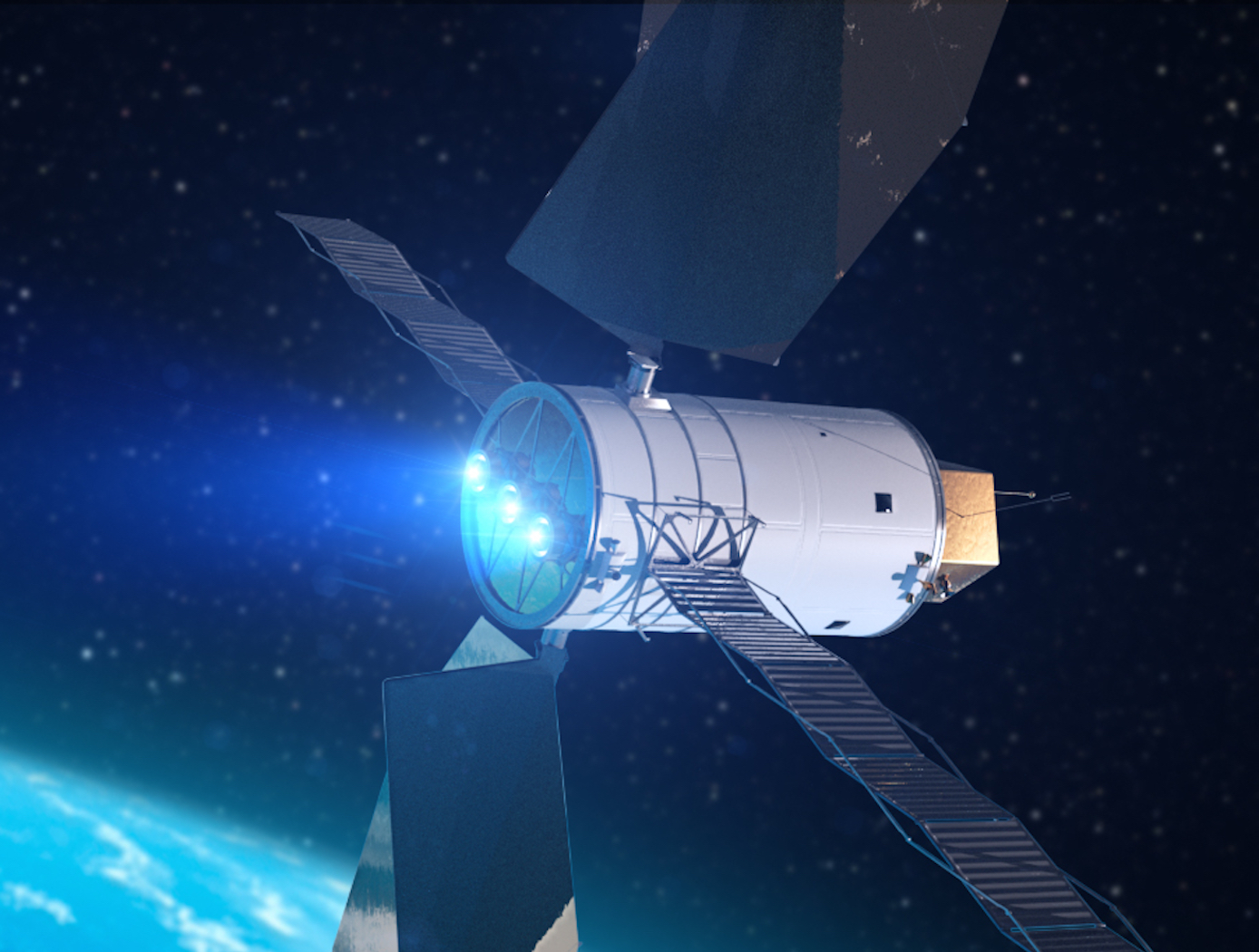
The NASA Glenn Research Center (GRC) has expertise in small spacecraft electric propulsion (SSEP). NASA's SSEP project is developing technologies critical to expanding spacecraft capabilities and enabling ambitious new missions into deep space. Advanced SSEP technologies are based on the use of exceptionally fuel-efficient electrostatic Hall effect thrusters with optimized magnetic shielding. Low-power, high-throughput SSEP dramatically increases the capabilities of small spacecraft, and advanced magnetic circuit designs result in game-changing thruster performance. These advances can maximize reliability while minimizing launch cost.
Innovators at GRC have developed a suite of SSEP technologies. GRC seeks commercial partners to help satisfy NASA exploration and science mission requirements while improving U.S. competitiveness in the global electric propulsion market and catalyzing innovation related to SSEP technology.
The Technology
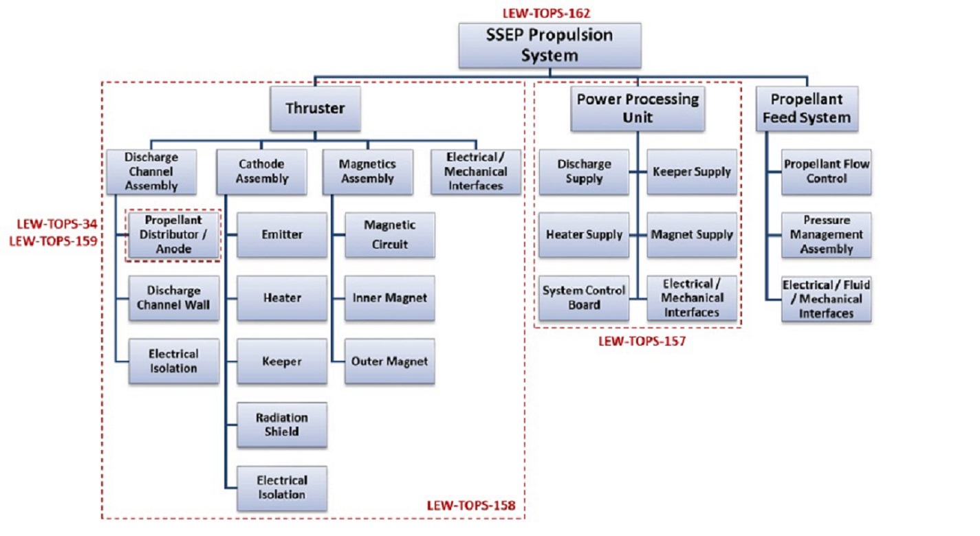
Innovators at GRC have developed a suite of SSEP technologies for small, low-power spacecraft using Hall effect thrusters including a high propellant throughput small spacecraft electric propulsion thruster (LEW-TOPS-158), a power processing unit for SSEP (LEW-TOPS-157), an anode manifold plug for Hall effect thrusters (LEW-TOPS-159), and additional Hall effect technologies (LEW-TOPS-34). See the Additional Information section at the bottom of the page for more information on each technology suite component.
GRC is making these technologies available to U.S. companies through a no-cost*, non-exclusive license agreement and companion Space Act Agreement. Licensees may receive a comprehensive package of design and process documents including issued and pending patents, design drawings, materials specifications, and test data. Licensees will assist in defining system requirements and creating new platforms to use the SSEP technologies. This streamlined, collaborative commercialization strategy helps satisfy NASA exploration and science mission requirements while improving U.S. competitiveness in the global electric propulsion market and improving the success of new electric propulsion developments. Working alongside our licensees, GRC hopes to generate a compendium of SSEP knowledge as a living document, maintained by all users in a consortia-like environment.
*Although the license and Space Act Agreement are no cost to the licensees, licensees would be responsible for setting up and maintaining an EAR restricted file sharing space.


Benefits
- Source of electric propulsion technology for small spacecraft: technologies related to low-power, high-propellant throughput Hall effect thrusters are available at no cost to U.S. companies
- High fuel economy: NASA's SSEP technology suite reduces the amount of propellant required onboard for deep space missions by up to 90% compared to chemical systems
- Reduced cost: allows deep space missions to carry more cargo and/or use smaller launch vehicles to reduce cost
Applications
- Aerospace: a propulsion system for small spacecraft using Hall effect thrusters
- Commercial space: small satellite constellations, station keeping, orbit raising, spacecraft servicing, missions beyond Low Earth Orbit/ Geosynchronous Equatorial Orbit
Technology Details
propulsion
LEW-TOPS-162
LEW-17678-1
LEW-19121-1
LEW-19121-2
LEW-19799-1
LEW-20035-1
LEW-20041-1
LEW-TOPS-157: Power Processing Unit (PPU) for Small Spacecraft Electric Propulsion
LEW-TOPS-158: High Propellant Throughput Small Spacecraft Electric Propulsion Thruster
LEW-TOPS-159: Anode Manifold Plug for Hall Effect Thrusters
LEW-TOPS-34: Hall Effect Thruster Technologies
Development of a High-Propellant Throughput Small Spacecraft Electric Propulsion System to Enable Lower Cost NASA Science Missions, Benavides, Gabriel F., et al, August 19, 2019
https://ntrs.nasa.gov/citations/20190030739
|
Tags:
|
|
|
Related Links:
|
Similar Results

High Propellant Throughput Small Spacecraft Electric Propulsion Thruster
NASAs High Propellant Throughput Small Spacecraft Electric Propulsion thruster offers a propellant throughput capability of greater than 120 kg with a nominal thruster efficiency greater than 50%. The new thruster design combines heritage Hall thruster component design approaches with recent NASA GRC advancements in the areas of advanced magnetic circuit design, robust propellant manifolds, and center mounted cathodes. Prototypes of the High Propellant Throughput Small Spacecraft Electric Propulsion thruster have been fabricated and proof-of-concept has been demonstrated.
A significant advancement in the High Propellant Throughput Small Spacecraft Electric Propulsion thruster is NASA's optimized magnetically shielded (OMS) field topology. The new OMS configuration reduces discharge channel erosion rates compared to conventional Hall thrusters, while reducing front pole cover erosion rates compared to traditional magnetically shielded Hall thrusters. This system also includes a largely unibody structure to reduce fabrication cost, increase strength, and optimize thermal management. A coupling plate between the high voltage discharge channel and low voltage thruster body allows more efficient thruster assembly and verification processes. Other design advancements further simplify assembly, improve robustness, and optimize performance.

Anode Manifold Plug for Hall Effect Thrusters
Flow-restricting features in a Hall thruster anode manifold assembly, typically precision manufactured orifices, can contribute to significant flow non-uniformity if tolerances on the features are not properly controlled. Non-uniformity in flow distribution negatively impacts thruster performance. The anode assembly is usually a complex and expensive assembly to manufacture. Removing the flow restricting elements from the anode manifold structure in favor of modular insertable subcomponents (i.e., plugs) enables the use of more reliable and repeatable precision manufacturing techniques. The resulting components can be tested, characterized, and sorted for acceptance before being installed into the larger anode assembly (i.e., quality control can be performed at the subcomponent level). This may lead to increased performance and yield rate of the final assembly.
The flow restrictor plugs can be made in many different ways. The most basic flow restrictor takes the form of a precision hole machined into a cylinder, where the cylinder is then press fit into a hole drilled into the anode base. Alternate embodiments of the flow restrictor include precision machined nozzles, laminar flow elements, or sintered porous metal elements. The flow restrictor can also be made from a different material than the anode base, such as a precision ruby orifice contained in a metal carrier which is installed in a metal anode base. The plugs can be installed in a variety of ways, all of which create hermetic seals. Installation can include a press fit relying on plastic deformation or threading the plug component into the anode base. Welding on the top surface of the anode base can also be done to provide a robust hermetic seal.

Power Processing Unit (PPU) for Small Spacecraft Electric Propulsion
Key subsystems of a scalable PPU for low-power Hall effect electric propulsion have been developed and demonstrated at NASA GRC. The PPU conditions and supplies power to the thruster and propellant flow control (PFC) components. It operates from an input voltage of 24 to 34 VDC to be compatible with typical small spacecraft with 28 V unregulated power systems. The PPU provides fault protection to protect the PPU, thruster, PFC components, and spacecraft. It is scalable to accommodate various power and operational requirements of low-power Hall effect thrusters. An important subsystem of a PPU is the discharge supply, which processes up to 95% of the power in the PPU and must process high voltage to accelerate thrust generating plasma. Each discharge power module in this PPU design is capable of processing up to 500 W of power and output up to 400 VDC. A full-bridge topology operating at switching frequency 50 kHz is used with a lightweight foil transformer. Two or more modules can operate in parallel to scale up the discharge power as required. Output voltage and current regulation controls allow for any of the common thruster start-up modes (hard, soft or glow).

Hall Effect Thruster Technologies
Used for propelling Earth-orbiting satellites and deep-space robotic vehicles, the HET gets its name because it traps electrons with an intense radial magnetic field in an azimuthal Hall current moving around the circumference of an annular ceramic channel. The electrons in the circulating Hall current ionize the onboard propellant - the inert gas xenon - and create an ionized plasma. The xenon plasma is then accelerated axially, via an applied electric field along the coaxial channel, to an exit velocity of up to 65,000 miles per hour to produce thrust. The interaction of the accelerated plasma and the downstream edge of the channel, where the plasma is the most energetic, results in erosion of the surrounding magnetic system used to generate the plasma. One of NASA Glenn's novel designs relies on an azimuthally symmetric configuration that minimizes radial magnetic fields at the discharge chamber walls. This configuration completely shields the walls of the discharge chamber from the high-energy plasma ions. With regard to the discharge-channel-wall replacement innovation, an actuator can be configured to extend the discharge chamber along the centerline axis. The actuator can be either mechanical or programmable. In either case, the sleeve can be extended while an upstream portion of the discharge chamber remains stationary, thereby preventing plasma exposure. These novel designs increase the efficiency and extend the lifetime of the HET to five times that of unshielded thrusters, enabling a new era of space missions.

High-Voltage Power System for Hybrid Electric Aircraft Propulsion
Glenn's novel system supports the NASA Aeronautics Research Mission Directorate (ARMD) strategic plan to leverage advancements in technologies over the next 25 years and beyond, leading to new aircraft configurations with enhanced performance, improved energy efficiency, and reduced CO2 emissions. The electric system is a multi-megawatt micro-grid that converts mechanical energy to electric via generators, and electric energy to mechanical via motor-driven fans. This innovation would use the variation in aircraft throttle settings to produce a high-voltage (20 kilovolts), variable-frequency 9-phase AC distribution system. Using doubly fed electric machines (generator, propulsor, and flywheel) allows for field excitation that can cause variable-frequency or variable speed operation around the commanded throttle setting. The flywheel enables an energy storage system that recovers and reuses energy, while the flywheel slews with the throttle control using the electromagnetic torque produced by the doubly fed electric machine. This design permits both sub-synchronous and super-synchronous operation using limited field excitation power provided through power converters. Finally, the reduced switchgear mass facilitated through the use of a high-frequency AC system, setting-less protection zones, and simplified switches for fault clearance provides enhanced operational capability. This system can be controlled so that fault energy is minimized, preventing collateral damage to aircraft structures even with high voltage distribution. Glenn's innovative system adds performance, efficiency, reliability, and cost savings to cutting-edge hybrid electric technology.
This is an early-stage technology requiring additional development, and Glenn welcomes co-development opportunities.


