Supersonic Spike Diffuser
mechanical and fluid systems
Supersonic Spike Diffuser (SSC-TOPS-10)
Double the pumping efficiency in one quarter the space.
Overview
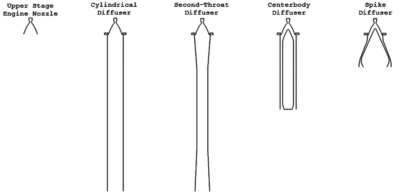
Standard cylindrical and second-throat diffusers allow supersonic gas flows to expand within their walls and pull a vacuum on any upstream void. However, the high-Mach-number shock reflections that occur in the center of the plume create substantial losses and result in an inefficient pumping process. Centerbody diffuser designs provide an improvement by reducing the maximum Mach number of the core flow, but also increase the number of oblique shocks in the system by introducing multiple turns into the system.
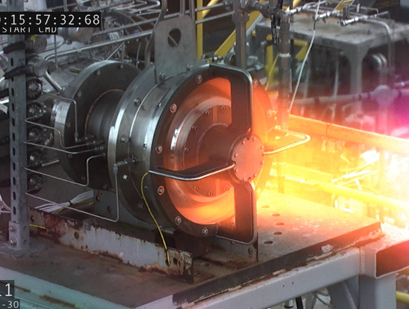
A new type of spike diffuser recently developed by NASA Stennis Space Center is able to provide approximately double the pumping performance of second-throat diffusers via Pareto-efficient reduction of both core Mach number and flow deflection. This enables substantially lower vacuum pressures to be achieved for a given feed pressure/mass flow via the use of higher-expansion-ratio driving nozzles. Spike diffusers are also spatially compact, requiring only ~25% of the length of second-throat designs
The Technology
The basic mode of operation for all passive supersonic diffusers is to enable a plumes inherent power to drive the outer boundary of the exhaust jet to the diffuser wall so that the entire cross-section of the flow has a speed greater than that of sound. This allows mass removal from the area surrounding the nozzle via entrainment. The result is a low-pressure environment similar to the altitude at which the nozzle was designed to operate. Additionally, the nature of supersonic flow prevents pressure interference from the downstream environment.
The specific geometry of each coupled nozzle-diffuser system dictates how efficiently it is able to operate, with the primary indicator of performance being the stagnation-to-ambient pressure ratio at which the plume attaches to the wall and starts the diffuser. Cylindrical diffusers simply provide a surface for plume attachment and have the worst performance of all geometries but are easy to construct. Second-throat diffusers are characterized by an additional area contraction which provides better resistance to ambient backpressure. Centerbody diffusers reduce shock losses by placing an aerodynamic obstruction in a cylindrical diffuser to prevent high Mach number plume expansion. They provide the best performance and smallest physical envelope of historically-used diffuser types. Spike diffusers are unconventional by comparison and are characterized by the use of an aerodynamic centerbody which expands beyond the diameter of the rocket itself, reducing high Mach number losses and a single turning of the entire core flow so that its velocity has a strong radial component. Additionally, they feature contouring of the surrounding aeroshell in a manner that provides an axial area ratio profile similar to that of second throat diffusers. By combining desirable aspects of the conventional diffuser types, they are able to provide the best overall aerodynamic performance in the smallest spatial envelope.


Benefits
- Starting pressure ratio ~50% of conventional diffuser geometries
- Lower vacuum achievable for a fixed feed pressure/mass flow
- Spatially compact
- Reduced structural overhead
Applications
- Altitude Simulation
- Steel Industry (Degassing)
- Chemical Processing (distillation, drying, stripping, evaporation, etc.)
- Oil and Gas Refinement (vacuum distillation)
- Edible Oil Processing (deodorization, hydrogenation, etc.)
- Artificial Fiber Manufacturing
- Flavors and Fragrances (vacuum distillation)
Technology Details
mechanical and fluid systems
SSC-TOPS-10
SSC-00573
Similar Results

Reverse Vortex Ring (RVR)
Vibration problems, which occur more frequently in high power to weight machines, often lead to costly down time, subsequent redesign, and, in some instances, catastrophic failure. A disproportionate number of vibration problems in rotating machinery can be attributed to highly pre-swirled fluid entering tight clearance locations such as seals and fluid bearings. The relationship between high fluid pre-swirl and undesirable vibration issues is clear. Machines with high levels of fluid pre-swirl are more susceptible to instabilities and vibration problems.
A top priority in rotor dynamic design, therefore, is to develop devices to minimize the level of fluid pre-swirl entering tight clearance locations. The RVR was designed to condition the flow prior to entering the seal (or axial flow fluid-film bearing) so that the flow through the annular clearance is at a minimum purely axial. While conventional swirl brakes have only been shown to reduce pre-swirl by up to 30%, the RVR can actually reverse the direction of the swirl, so that circumferential fluid velocity flows in a direction counter to shaft rotation. Thus, a classic detriment to rotating machinery has now become an asset to ameliorate vibration issues through the RVR.
The RVR is axially efficient, typically increasing the axial length of a smooth annular seal on the order of 10-12%.
The RVR has been extensively tested and is now in use at NASA.

Supersonic Laminar Flow Control
This technique injects precisely defined stationary transient growth disturbances into the free air slipstream over a wing that develop into streamwise elongated "streaks." These streaks are created with an alternating pattern of low and high streamwise velocity in the boundary layer flow adjacent to the aerodynamic surface of interest. Judicious selection of streak wavelength, amplitude, and profile allows the first-mode instability waves responsible for transition via oblique mode breakdown to be damped while the remaining, uncontrolled waves are kept below an amplification threshold. A similar control concept is also applicable to second mode transition at hypersonic Mach numbers.

Autonomous Slat-Cove Filler Device
NASA Langley designed the shape memory alloy slat-cove filler to provide significant broad-band noise reduction to any aircraft wing structure that has a leading-edge, high-lift device and that is distinct from the main-wing element. The design can be retrofitted to existing aircraft structures and can be easily incorporated into the existing or future designs for aircraft wing structures. The concept involves very few components, requires no additional mechanical support from pneumatic or hydraulic systems, and makes use of existing slat-actuation systems for retraction. The design is autonomous, simple, and constitutes low-weight addition. The concept is also considered fail-safe because the lift would not be diminished in the event that the slat cove filler failed to deploy.
Several advancements have been devised to accommodate complex features encountered in application to practical airframe structures. Graphics from a computational model of a 2D physical demonstration system show the configuration and strain in the slat-cove filler in the deployed and stowed conditions. Features enabling stowage of a large curvilinear length (sliding hinge) and maintenance of the optimized outer mold line (auxiliary component) are highlighted. Other advancements for application to 3D, flight airframes are visible in the image from a model for one entire section of a slat-cove-filler treatment for a wide-body, transport-class aircraft.
NASA Langley also offers a design for a deformable structure that is deployed from the leading edge of the main-wing element, termed the slat-gap filler. It closes and covers the gap between the slat and the main-wing element, but can be readily and autonomously opened in emergency to regain the baseline high-lift configuration and its corresponding lift performance at high angles of attack. This approach has similar benefits as the slat-cove filler device.

Improving Hybrid Electric Propulsion Efficiency
Electrically driven turbine engine compressor and propulsion fans require a large stability margin against stall conditions to avoid unwanted performance issues while undergoing transients in operating conditions. This stability margin, while it maintains safe operation, also necessarily reduces the engine performance. Despite extensive research efforts, no viable alternative methods for reducing the operable stability margin and improving engine performance exist. This current innovation, originally conceived for stall prevention, offers a solution by utilizing a supercapacitor in line with an electric motor and motor controller to rapidly change a compressor or propulsor fan speed. The use of the supercapacitor enables rapid extraction, or addition of power, to prevent the fan from stalling.
Additionally, this novel drive motor may be used for sensing stall event precursor signals by using the motor controller to detect variations in torque on the shaft caused by variance in loading on the blade system. The improved stall avoidance capabilities allow an engine fan to operate more efficiently, providing more thrust for a given frontal area, increasing operational range, reduced weight, and improved operational safety.
The related patent is now available to license. Please note that NASA does not manufacture products itself for commercial sale.

Variable-Aperture Reciprocating Reed (VARR) Valve
The VARR valve has been designed to provide a variable-size aperture that proportionately changes in relation to gas flow demand. When the pressure delta between two chambers is low, the effective aperture cross-sectional area is small, while at high delta pressure the effective aperture cross-sectional area is large. This variable aperture prevents overly restricted gas flow. As shown in the drawing below, gas flow through the VARR valve is not one way. Gas flow can traverse through the device in a back-and-forth reversing flow manner or be used in a single flow direction manner. The contour shapes and spacing can be set to create a linear delta pressure vs. flow rate or other pressure functions not enabled by current standard orifices. Also, the device can be tuned to operate as a flow meter over an extremely large flow range as compared to fixed-orifice meters. As a meter, the device is capable of matching or exceeding the turbine meter ratio of 150:1 without possessing the many mechanical failure modes associated with turbine bearings, blades, and friction, etc.


