Search
aerospace
Outer Aileron Yaw Damper
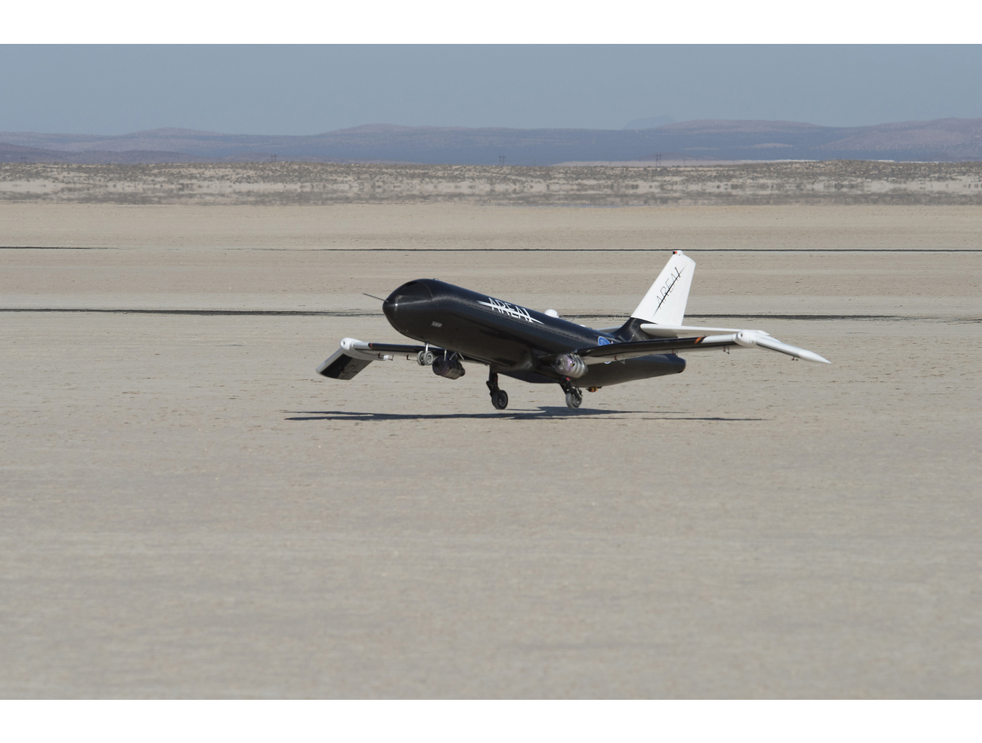
Rudders have long served as the primary flight control surface as is pertains to aircraft yaw. Breaking this mold, NASA's SAW technology is a game-changing development in aircraft wing engineering that reduces rudder motion required to control aircraft. The benefits of reduced rudder dependency led NASA to develop the outer aileron yaw damper to further decrease or eliminate rudder dependency for aircraft using SAWs.
As mentioned, SAWs use shape memory alloy actuators to articulate the outer portion of the wing, effectively creating a movable wingtip. NASA's invention uses an outer aileron located on the wingtips, which is driven (along with the inner ailerons) by a novel control algorithm. The control algorithm, taking into account the wingtip positions, manipulates the outer ailerons to achieve the desired yaw rate. At the same time, it positions the inner ailerons to counter roll rate resulting from the outer aileron. In other words, the control algorithm calculates a control surface ratio (i.e., position of inboard aileron and outboard aileron) that produces desired yaw and roll accelerations.
The system can also be used to offset the existing rudder in current or future aircraft designs. A second part of NASAs novel outer aileron control algorithm modifies the aircrafts rudder loop gain in proportion to outer aileron usage. This allows the outer ailerons and rudder to work in tandem, while at the same time reducing rudder usage.
As a result of this NASA invention, required rudder usage can be reduced or eliminated for aircraft with SAWs. Consequently, the size of rudders and vertical tail structures can be reduced, which in turn reduces weight and parasitic drag. The result is an aircraft with increased performance and fuel efficiency.
Propulsion

A New Twist Makes Rotating Machinery More Efficient and Quieter
Derived from a design approach for a new wing known as PRANDTL-D, this technology achieves similar improvements for propellers and other rotating machinery.
<b><em>How It Works</b></em>
To achieve the innovation's alternate spanload, Armstrong designers applied a non-linear twist to the propeller blade. The twist moves the load inward and dissipates the tip vortex over a wider area, minimizing its effect on drag. It also results in a decrease in load at the tip and reduced torque at the tip. These changes combine to achieve a dramatic reduction in power consumption without compromising the blade's other parameters. Specifically, the blade's diameter and rpm remain unchanged.
<b><em>What Makes It Better</b></em>
Unlike the conventional minimum induced loss (elliptical) spanload, which consumes large amounts of power at the tip of the blade, the new design unloads the tip and reduces torque, achieving significant improvements in efficiency. First-order analysis shows a more than 15 percent improvement in power consumption while producing the same thrust. The design also produces significantly less noise than conventional blade designs.
aerospace

Methods for Predicting Transonic Flutter Using Simple Data Models
Transonic flutter is a pacing item in transport aircraft design in that it is crucial to characterize this phenomenon for each aircraft to prevent catastrophic failure. Aerodynamic study of flows around airfoils is a canonical problem that entails both experimental and computational approaches. While the transonic flutter prediction can be more accurate with high-fidelity Computational Fluid Dynamics (CFD) methods than with unsteady potential flow methods, the computational cost is high. Therefore, computationally efficient methods for transonic flutter prediction continue to be of high interest to the aircraft design community. NASA Ames has developed a novel method that eliminates the need for expensive calculations of aerodynamics of wing flutter, which typically takes tens of hours on a supercomputer. Such calculations are now replaced by machine-learning-based closed form solutions that provide the solution almost instantaneously. The technology presents a new approach to predict the flow around pitching NACA00 series airfoils. NACA airfoils are generally symmetric, and thus they do not possess camber. However, the invention can readily extend to wings with camber. This novel data modeling approach is orders of magnitude faster than the traditional CFD approach of predicting aerodynamic effects of transonic pitching airfoils. The data model is based on a subset of unsteady CFD simulations that train the model. The trained model then resolves the pitching airfoil in time for any other set on the order of a second, as compared with a complete CFD simulation that typically takes 30 hours on a supercomputer. The data model is demonstrated in this invention for transonic flow corresponding to Mach number of 0.755 over pitching NACA00 series airfoils for a reduced frequency range typical of flutter, i.e., k lies in the range 0.02 - 0.25.
aerospace
Improved Fixed-Wing Gust Load Alleviation Device
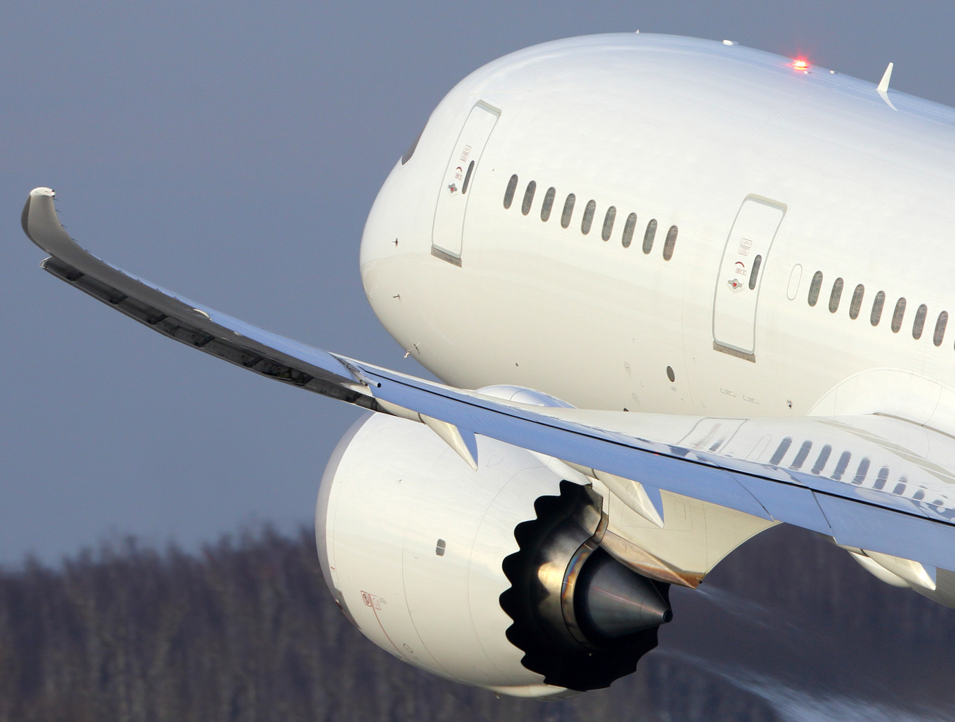
Gust loads may have detrimental impacts on flight including increased structural and aerodynamic loads, structural deformation, and decreased flight dynamic performance. This technology has been demonstrated to improve current gust load alleviation by use of a trailing-edge, free-floating surface control with a mass balance. Immediately upon impact, the inertial response of the mass balance shifts the center of gravity in front of the hinge line to develop an opposing aerodynamic force alleviating the load felt by the wing. This passive gust alleviation control covering 33% of the span of a cantilever wing was tested in NASA Langleys low speed wind tunnel and found to reduce wing response by 30%.
While ongoing experimental work with new laser sensing technologies is predicted to similarly reduce gust load, simplicity of design of the present invention may be advantageous for certification processes. Additionally, this passive technology may provide further gust alleviation upon extending the use of the control to the entire trailing edge of the wing or upon incorporation with current active gust alleviation systems.
Importantly, the technology can be easily incorporated into to the build of nearly all fixed wing aircrafts and pilot control can be maintained through a secondary trim tab. Though challenging to retrofit, passive gust alleviation could enable use of thinner, more efficient wings in new plane design.
Information Technology and Software
Rapid Aero Modeling for Computational Experiments
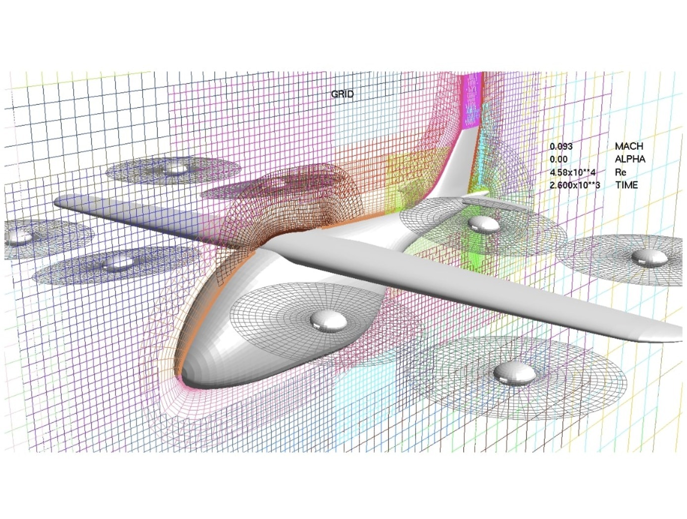
RAM-C interfaces with computational software to provide test logic and manage a unique process that implements three main bodies of theory: (a) aircraft system identification (SID), (b) design of experiment (DOE), and (c) CFD. SID defines any number of alternative estimation methods that can be used effectively under the RAM-C process (e.g., machine learning techniques, regression, neural nets, fuzzy modeling, etc.). DOE provides a statistically rigorous, sequential approach that defines the test points required for a given model complexity. Typical DOE test points are optimized to reduce either estimation error or prediction error. CFD provides a large range of fidelity for estimating aircraft aerodynamic responses. In initial implementations, NASA researchers “wrapped” RAM-C around OVERFLOW, a NASA-developed high-fidelity CFD flow solver. Alternative computational software requiring less time and computational resources could be also utilized.
RAM-C generates reduced-order aerodynamic models of aircraft. The software process begins with the user entering a desired level of fidelity and a test configuration defined in terms appropriate for the computational code in use. One can think of the computational code (e.g., high-fidelity CFD flow solver) as the “test facility” with which RAM-C communicates with to guide the modeling process. RAM-C logic determines where data needs to be collected, when the mathematical model structure needs to increase in order, and when the models satisfy the desired level of fidelity.
RAM-C is an efficient, statistically rigorous, automated testing process that only collects data required to identify models that achieve user-defined levels of fidelity – streamlining the modeling process and saving computational resources and time. At NASA, the same Rapid Aero Modeling (RAM) concept has also been applied to other “test facilities” (e.g., wind tunnel test facilities in lieu of CFD software).
aerospace

Vertiport Assessment and Mobility Operations System (VAMOS!)
The term Advanced Air Mobility (AAM) refers to a new mode of transportation utilizing highly automated airborne vehicles for transporting goods and/or people. The adoption of widespread use of AAM vehicles will necessitate a network of vertiports located throughout a geographical region. A vertiport refers to a physical structure for the departure, arrival, and parking/storage of AAM vehicles. NASA-developed Vertiport Assessment and Mobility Operations System (VAMOS!) enables identifying geographical locations suitable for locating a vertiport or assessing suitability of pre-selected locations. For example, suitability evaluation factors include zoning, land use, transit stations, fire stations, noise, and time-varying factors like congestion and demand.
The vertiport assessment system assigns suitability values to these factors based on user-input, and types, including location-based (e.g., proximity to mass transit stations), level-based (e.g., noise levels), characteristic-based (e.g., residential zoning), and time-based (e.g., demand). Based on user input, the system spreads a grid over the geographical area, specifies importance criteria and weights for scaling the impact of the suitability factors, and identifies specific sub-regions as candidate locations. The candidate sub-regions are shown on a user interface map overlay in a color-coded gradient that reflects the suitability strength for a sub-region. Vertiport locations are selected within these sub-regions. These candidate vertiport locations are refined by establishing feasibility of flight between them. VAMOS! includes a modeling component and a simulation component. The modeling component assists a user to identify one or more geographical locations at which a vertiport may be physically built. The simulation component of the technology displays, in real-time, the simulated operational behavior of AAM vehicles and in the context of their projected flight paths combined with data dynamically obtained from live sources. These data sources can be from the Federal Aviation Administration (FAA) or other private or public governing bodies, from one or more AAM vehicles in flight, and from weather sources.
materials and coatings
Self-Healing Aluminum Metal Matrix Composite (MMC)
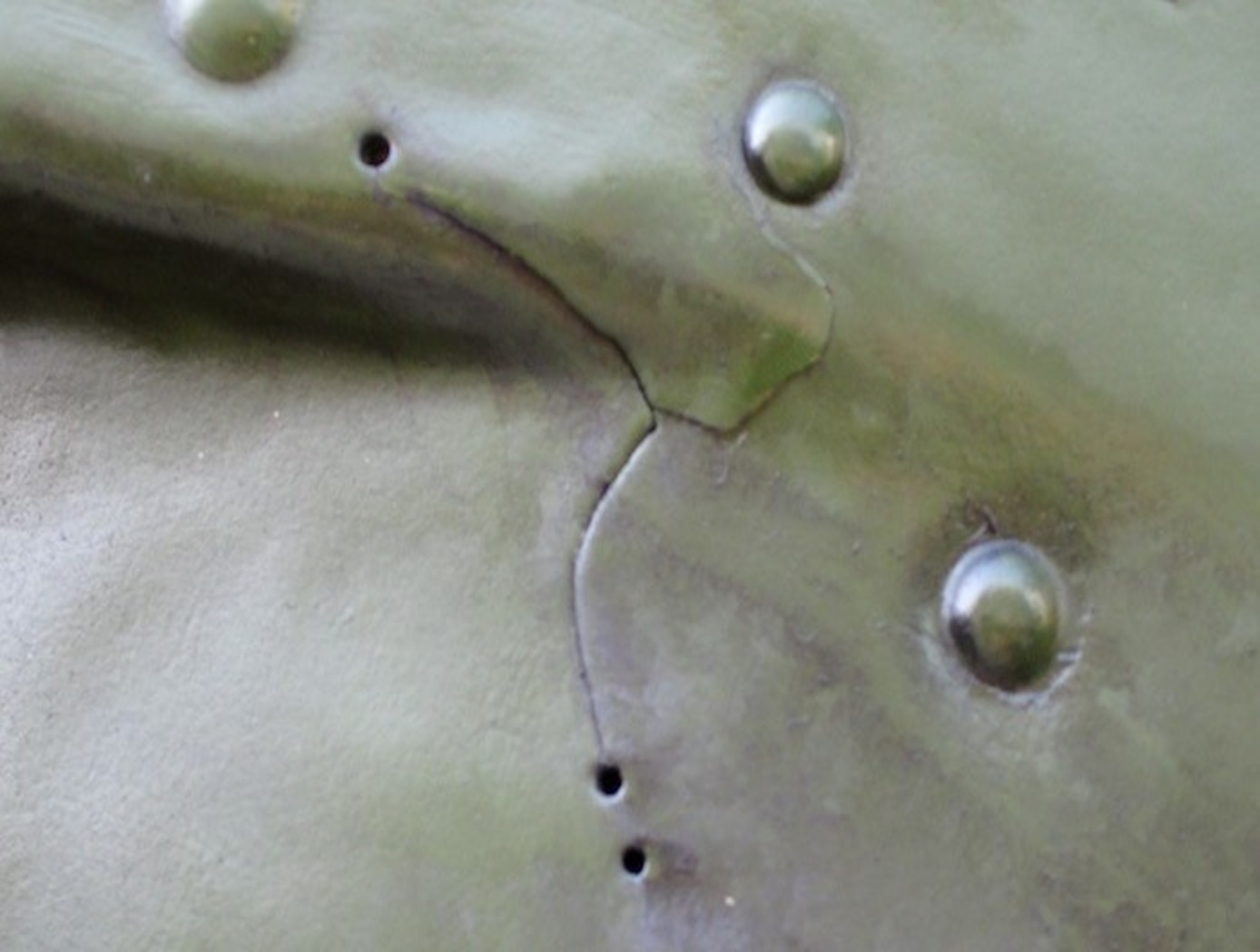
This materials system is comprised of an Al metal matrix with high-performance SMA reinforcements. The combination of the unique matrix composition and SMA elements allow for this material system to self-repair via a two-step crack repair method. When a crack is present in the matrix material, the MMC is heated above the SMA's austenite start (As) temperature. This initiates shape recovery of the SMA, pulling the crack together as the SMA reinforcements return to their initial length. Concurrently, the increased temperature causes softening and liquefaction of the eutectic micro-constituent in the matrix, which enables the recovery of plastic strain in the matrix as well as crack filling. Combined with the crack closure force provided by the SMA reinforcements completely reverting to their original length, the MMC welds itself together and, upon cooling, results in a solidified composite able to realize its pre-cracked, original strength. The research team has demonstrated and tested the new materials. The team induced cracks in prototype materials based on Al-Si matrix with SMA (NiTi) reinforcements and demonstrated the recovery of tensile strength after healing. Data from tensile and fatigue tests of the samples before and after the fatigue crack healing shows a 91.6% healing efficiency on average under tensile conditions.
Aerospace

Wind-Optimal Cruise Airspeed Mode for Flight Management Systems (FMS)
The novel approach for optimizing airspeed for both actual and predicted wind conditions in electric Vertical Takeoff and Landing (eVTOL) aircraft with Distributed Electric Propulsion (DEP) systems includes the process of creating a lookup table for wind‐optimal airspeed as a function of wind magnitude, considering the direction of the wind relative to the cruise segment, considering the cruise altitude for an aircraft type, and incorporating the wind-optimal airspeed lookup table in the performance database for real‐time access by the Flight Management Systems (FMS) to predict wind-optimal airspeed at waypoints of the flight plan. The target wind‐optimal airspeed is updated in real-time throughout the cruise portion of a flight.
In a test of the wind-optimal airspeed targeting technique using a multi-rotor aircraft model, results obtained show benefits of flying at the wind‐optimal cruise airspeed compared to the best‐range airspeed. In headwind conditions, energy consumption was reduced by up to 7.5%, and flight duration was reduced by up to 28%. Under uncertain wind magnitudes, flying at wind-optimal airspeed offered lower variability and higher predictability in energy consumption than flying at best‐range airspeed.
Mechanical and Fluid Systems
Active Flow Control System for Simple-hinged Flaps
Although simple-hinged flaps represent optimal high-lift systems for reducing cruise drag, previous attempts to design flow control systems enabling such technology in transport aircraft have been unsuccessful. This is largely because such systems generally require a tradeoff between (a) the ability to achieve the required lift performance, and (b) possessing sufficiently low pneumatic power to enable feasible aircraft system integration (i.e., avoiding excess weight penalties associated with high pneumatic power). For example, electrically powered AFC systems (e.g., plasma actuators, synthetic jet actuators) have practical power requirements, but with limited control authority, making such systems ineffective for highly deflected flaps. On the other hand, circulation control systems can provide necessary lift for airfoils or wings with high flap deflections, but require too much pneumatic power for aircraft integration. NASA’s HELP AFC system represents a breakthrough in flow separation control technology – to efficiently achieve necessary lift performances while requiring low pneumatic power relative to alternative flow control techniques.
NASA’s HELP AFC system uses a unique two-row actuator approach comprised of upstream sweeping jet (SWJ) actuators and downstream discrete jets, which share the same air supply plenum. The upstream (row 1) SWJ actuators provide good spanwise flow-control coverage with relatively mass flow, effectively pre-conditioning the boundary layer such that the downstream (row 2) discrete jets achieve better flow control authority. The two row actuator system, working together, produce a total aerodynamic lift greater than the sum of each row acting individually. The result is a system that generates sufficient lift performance for simple-hinged flaps with pneumatic power requirements low enough to enable aircraft integration.
Aerospace

Active Turbulence Suppression System for Electric Vertical Take-Off and Landing (eVTOL) vehicles
The Active Turbulence Suppression (ATS) system for electric Vertical Take-Off and Landing (eVTOL) vehicles employ existing lifting propellers to dampen instabilities during flight, such as Dutch-roll oscillations and other gust-induced oscillations. When a roll angle of an eVTOL aircraft has deviated or is about to deviate from a current stable aircraft state to an undesirable, unstable, and oscillating aircraft state, the ATS system queries a turbulence suppression database that stores a set of propeller speed profiles for mitigation a deviation of a given roll angle for a particular aircraft with specified propellers. Using this data, the eVTOL flight controller adjusts the speed of the propellers for a certain duration of time, according to the propeller speed profiles for mitigating the deviation. In models of aircraft with adjustable propeller angles, the database includes blade angle profiles for mitigating the effects of turbulent conditions. Timing and rate of propeller activation can be pre-computed using higher order computational modeling performed with NASA’s super computing resources. Because the data is pre-computed, the use of the ATS system onboard does not require significant computing resources to implement on eVTOL vehicles. The technology, a mechanism by which existing eVTOL propellers are leveraged to suppress gust-induced oscillations enables a safe and comfortable passenger experience at low-cost and without added hardware.


