Search
Electrical and Electronics

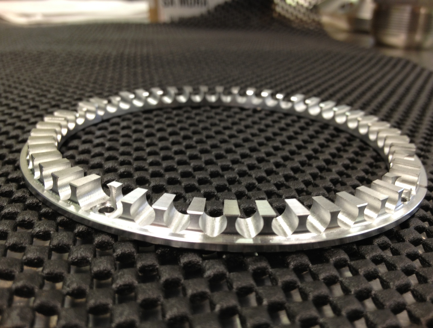
Self-Adjusting Gap System for Charge Mitigation and Monitoring
Fixed-point or spark-plug discharge systems are challenging to set up and maintain, often suffering from performance degradation or failure as repeated discharges damage and alter contact points. Similarly, contact-based solutions like slip rings can introduce torque drag and create contamination particles over time as materials wear down. The SAG system eliminates these problems with its innovative contactless design, proven to cycle reliably tens of thousands of times without failure. In testing, this system survived approximately 25,000 times the expected mission charge cycles.
The SAG system consists of a flexure, discharge point, and bleed circuit that controls the voltage, location and current at which a discharge occurs. The flexure is electrically isolated from the rest of the stationary body forcing the discharge current to go through the bleed circuit. This provides the ability to protect sensitive electronics from a sudden field collapse or ground plane disturbance. The flexure is able of taking different forms depending on the application and desired characteristics allowing for a scalable system, modifiable for various mission parameters. Additionally, the SAG system is passive until needed, requiring no active electronics unless used as a sensor. Due to its contactless nature, the SAG system simplifies live wear testing, significantly lowering costs compared to traditional mechanisms. Unlike fixed-point systems, it does not require precise dynamic clearances, making it more tolerant to launch loads and reducing the severity of electrical discharge events.
Although designed for space and planetary exploration applications, the SAG system may also be valuable for terrestrial use cases for monitoring charging of electrically isolated components where charge buildup may occur or where grounding isn’t possible. The SAG System is at technology readiness level (TRL) 6 (system demonstration in relevant environment) and is available for patent licensing.
mechanical and fluid systems
Reverse Vortex Ring (RVR)
Vibration problems, which occur more frequently in high power to weight machines, often lead to costly down time, subsequent redesign, and, in some instances, catastrophic failure. A disproportionate number of vibration problems in rotating machinery can be attributed to highly pre-swirled fluid entering tight clearance locations such as seals and fluid bearings. The relationship between high fluid pre-swirl and undesirable vibration issues is clear. Machines with high levels of fluid pre-swirl are more susceptible to instabilities and vibration problems.
A top priority in rotor dynamic design, therefore, is to develop devices to minimize the level of fluid pre-swirl entering tight clearance locations. The RVR was designed to condition the flow prior to entering the seal (or axial flow fluid-film bearing) so that the flow through the annular clearance is at a minimum purely axial. While conventional swirl brakes have only been shown to reduce pre-swirl by up to 30%, the RVR can actually reverse the direction of the swirl, so that circumferential fluid velocity flows in a direction counter to shaft rotation. Thus, a classic detriment to rotating machinery has now become an asset to ameliorate vibration issues through the RVR.
The RVR is axially efficient, typically increasing the axial length of a smooth annular seal on the order of 10-12%.
The RVR has been extensively tested and is now in use at NASA.

