Search
manufacturing
Fiber-Metal Laminate Manufacturing Technique
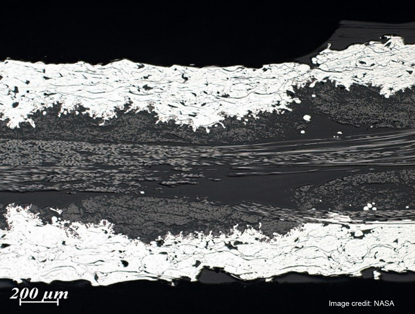
Fiber-Metal Laminates (FMLs) are composite materials that consist of conventional fiber reinforced plastics with the addition of a metal component, typically a foil or mesh layer(s). The metal component offers the advantage of incorporating metal-like properties to the composite construction. While a range of potential advantages and applications have been discussed for FMLs, the primary application to date has been for aircraft structures, with one potential advantage being the lightning strike protection (LSP) offered by the improved electrical conductivity. As aircraft construction has moved to composite structures, there has been an increasing need for such conductive composites. Similarly, with increasing use of composites for other large structures, e.g. wind turbines, there are an increasing number of potential applications for lightning strike protection materials. Other advantages of FML are improved impact and fire resistance.
This innovation provides a method for making FML materials that incorporate nanotube reinforcement. The method involves the use of RF plasma spray to directly form and deposit nanotube materials onto fibers/fabrics, which can then be manufactured into composite structures by infiltrating the fiber with resin, and consolidating the structure via autoclave processing or via the use Vacuum Assisted Resin Transfer Molding (VARTM) composite manufacturing methods. Nanotubes incorporated into the structure in this manner can be of several types, for example boron nitride or carbon nanotubes. The objective of this innovation is to incorporate the nanotube materials in the FML in order to improve the mechanical properties.
manufacturing
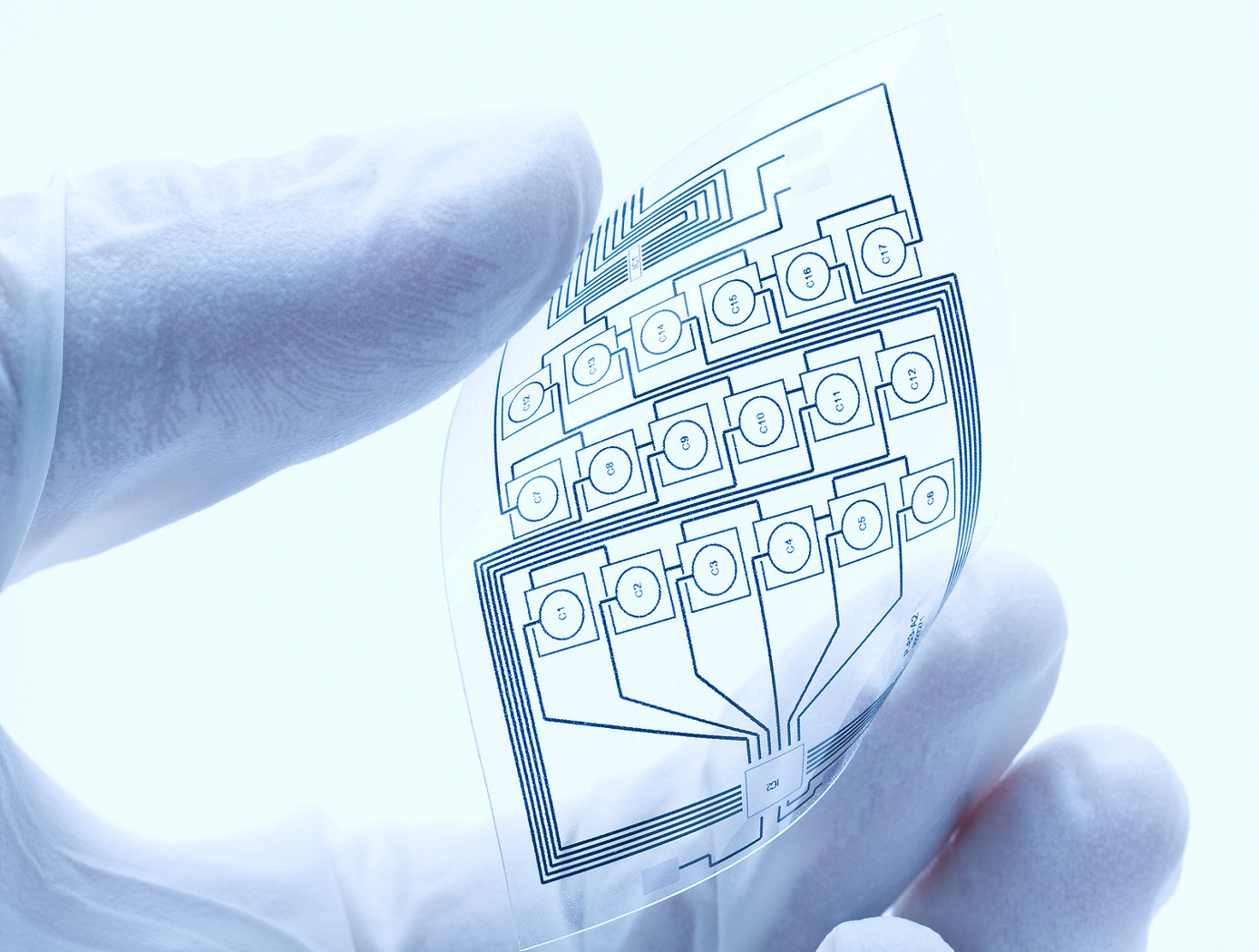
Fabricating printable electronics and biosensor chips
The plasma system consists of a glass tube with a diameter of 0.5 mm or larger, if desired. The electrodes are separated by 10 mm. Helium, argon or cold dry air can be used as a plasma gas source. An applied high voltage between the electrodes causes the gas to breakdown within the central core of the glass capillary generating atmospheric plasma. Nanostructures colloids/organic/inorganic precursors are placed in a glass container with an inlet and outlet for carrier gas and are seated on an ultrasonic nebuliser. The aerosol is then carried into the plasma stream by the carrier gas and is deposited.
The atmospheric plasma deposition system can be modified for depositing multiple materials, either simultaneously or sequentially, and for high-throughput processing by having multiple jets. Each capillary can either be connected to the container containing a single precursor material or to different containers containing different precursor materials to facilitate multiple depositions. The multi-jet plasma system can be automated and controlled individually to precisely control surface characteristics. This technique is independent of the chosen substrate, and has proven to work for many substrates, including paper, plastic, semiconductors and metals.
Environment

Carbon Capture Filter
NASA’s Carbon Capture Filter was designed to trap solid carbon dust through a variety of mechanisms. These include inertial separation, flow recirculation, flow tortuosity, media filtration, and quenching of hot particles or of precursor particles from pyrolysis. The filter uses a custom-designed housing to produce a strong and large recirculating pattern to remove dust through inertial forces and confine it into a large collection cup, which is enshrouded in a cold trap (using a thermoelectric cooler) to thermally induce precipitation of the solid carbon. The flow then passes through a single stage baffle and tube filters before exiting through the outlet at the top of the housing.
During operations, gaseous carbon-containing streams enter the filter via an inlet tube at the top of the housing. The inlet tube extends down towards the bottom of the collection cup, where the high-speed stream meets a sudden perpendicular bottom wall, inducing a stagnation flow. Large particles inertially separate from the flow and impinge onto the bottom wall. The partial enclosure of the collection cup (aside from a small slit connecting it to the upper chamber) causes a recirculation bubble to form, increasing the residence time of the stream. The vortical motion of the recirculation bubble causes the large particles to spin outwards towards the walls of the collection cup. The collection cup is cooled to quench the carbon particles, causing them to precipitate out and collect on the walls of the cup. The extended residence time caused by the recirculating flow further quenches the stream. Only small particles that are entrained sufficiently by the flow make it through the slit between the collection cup and upper chamber. On the top wall of the upper chamber, an array of tubular filters collects the remaining particles before the gaseous stream exits the system.
NASA’s Carbon Capture Filter has been prototyped and undergone initial testing with simulant dust, yielding promising results. The invention is available for licensing to industry.
mechanical and fluid systems
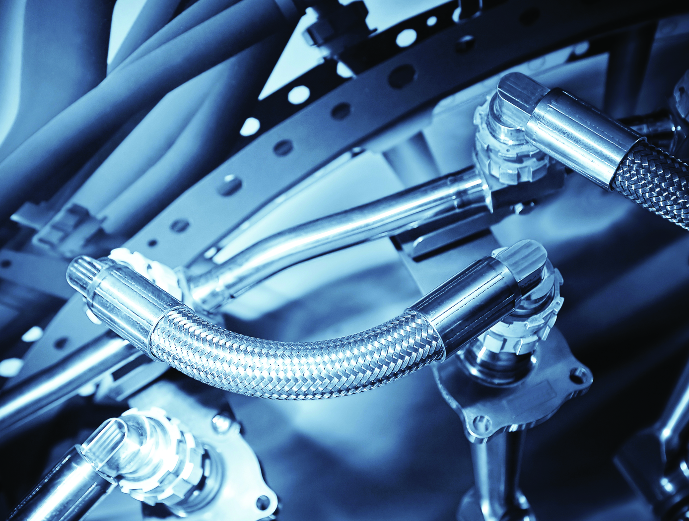
Low-Cost, Long-Lasting Valve Seal
NASA's technique simplifies the seat installation process by requiring less installation equipment, eliminating the need for unnecessary apparatus such as fasteners and retainers. Multiple seals can be installed simultaneously, saving both time and money.
NASA has tested the long-term performance of a solenoid actuated valve with a seat that was fitted using the new installation technique. The valve was fabricated and tested to determine high-cycle and internal leakage performance for an inductive pulsed plasma thruster (IPPT) application for in-space propulsion. The valve demonstrated the capability to throttle the gas flow rate while maintaining low leakage rates of less than
10<sup>-3</sup> standard cubic centimeters per second (sccss) of helium (He) at the beginning of the valves lifetime. The IPPT solenoid actuated valve test successfully reached 1 million cycles with desirable leakage performance, which is beyond traditional solenoid valve applications requirements. Future design iterations can further enhance the valve's life span and performance.
The seat seal installation method is most applicable to small valve instruments that have a small orifice of 0.5 inches or less.
Power Generation and Storage

ThermoArc Facilitates Low-Cost Li-Ion Battery Testing
For years, NASA and the battery industry have been improving passive propagation resistant (PPR) Li-ion battery cell technology by enhancing their material and design choices. These efforts help ensure that a single cell’s TR event does not overheat adjacent cells or the entire battery pack ultimately causing fire or explosion. To improve cell integrity, single cells within battery packs are triggered into TR so that the battery pack can be analyzed for its TR resistance.
ThermoArc operates by initiating a plasma arc, capable of delivering thermal energy up to 100W, to a very small (1mm diameter) section of the cell. The extremely localized high heat flux rapidly degrades a small section of the internal cell separator, resulting in a short circuit that leads to TR. This technology comprises several components: a high-turn-ratio step-up transformer capable of producing a minimum of 1,000 V upon the secondary winding, an H-bridge electronic circuit to drive the transformer on the primary side, two tungsten electrodes to deliver the plasma arc, and a power supply unit.
ThermoArc applications may exist in any Li-ion battery cell/pack testing application where TR must be induced in an individual cell. Such applications could include testing of PPR battery packs to ensure single cell runaway does not cause catastrophic damage, more general battery destructive testing designed to better understand battery failure states, or other experimental testing. Companies interested in licensing this innovation may include those that manufacture internal short-circuit (ISC) cells or other devices used to induce TR at the individual cell level, battery testing firms, and Li-ion battery manufacturers with a focus on Li-ion battery packs for critical applications.
ThermoArc is at a technology readiness level (TRL) 5 (component and/or breadboard validation in laboratory environment) and is now available for patent licensing. Please note that NASA does not manufacture products itself for commercial sale.

