Search

manufacturing
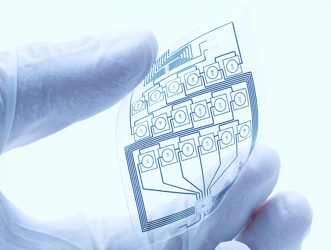
Atmospheric Pressure Plasma Based Fabrication of Printable Electronics and Functional Coatings
Fabricating printable electronics and biosensor chips
The plasma system consists of a glass tube with a diameter of 0.5 mm or larger, if desired. The electrodes are separated by 10 mm. Helium, argon or cold dry air can be used as a plasma gas source. An applied high voltage between the electrodes causes the gas to breakdown within the central core of the glass capillary generating atmospheric plasma. Nanostructures colloids/organic/inorganic precursors are placed in a glass container with an inlet and outlet for carrier gas and are seated on an ultrasonic nebuliser. The aerosol is then carried into the plasma stream by the carrier gas and is deposited. The atmospheric plasma deposition system can be modified for depositing multiple materials, either simultaneously or sequentially, and for high-throughput processing by having multiple jets. Each capillary can either be connected to the container containing a single precursor material or to different containers containing different precursor materials to facilitate multiple depositions. The multi-jet plasma system can be automated and controlled individually to precisely control surface characteristics. This technique is independent of the chosen substrate, and has proven to work for many substrates, including paper, plastic, semiconductors and metals.
instrumentation
3D Laser Scanner
ShuttleSCAN 3-D
How It Works The scanners operation is based on the principle of Laser Triagulation. The ShuttleSCAN contains an imaging sensor; two lasers mounted on opposite sides of the imaging sensor; and a customized, on-board processor for processing the data from the imaging sensor. The lasers are oriented at a given angle and surface height based on the size of objects being examined. For inspecting small details, such as defects in space shuttle tiles, a scanner is positioned close to the surface. This creates a small field of view but with very high resolution. For scanning larger objects, such as use in a robotic vision application, a scanner can be positioned several feet above the surface. This increases the field of view but results in slightly lower resolution. The laser projects a line on the surface, directly below the imaging sensor. For a perfectly flat surface, this projected line will be straight. As the ShuttleSCAN head moves over the surface, defects or irregularities above and below the surface will cause the line to deviate from perfectly straight. The SPACE processors proprietary algorithms interpret these deviations in real time and build a representation of the defect that is then transmitted to an attached PC for triangulation and 3-D display or printing. Real-time volume calculation of the defect is a capability unique to the ShuttleSCAN system. Why It Is Better The benefits of the ShuttleSCAN 3-D system are very unique in the industry. No other 3-D scanner can offer the combination of speed, resolution, size, power efficiency, and versatility. In addition, ShuttleSCAN can be used as a wireless instrument, unencumbered by cables. Traditional scanning systems make a tradeoff between resolution and speed. ShuttleSCANs onboard SPACE processor eliminates this tradeoff. The system scans at speeds greater than 600,000 points per second, with a resolution smaller than .001". Results of the scan are available in real time, whereas conventional systems scan over the surface, analyze the scanned data, and display the results long after the scan is complete.
Stay up to date, follow NASA's Technology Transfer Program on:
facebook twitter linkedin youtube
Facebook Logo Twitter Logo Linkedin Logo Youtube Logo