Search
Robotics Automation and Control
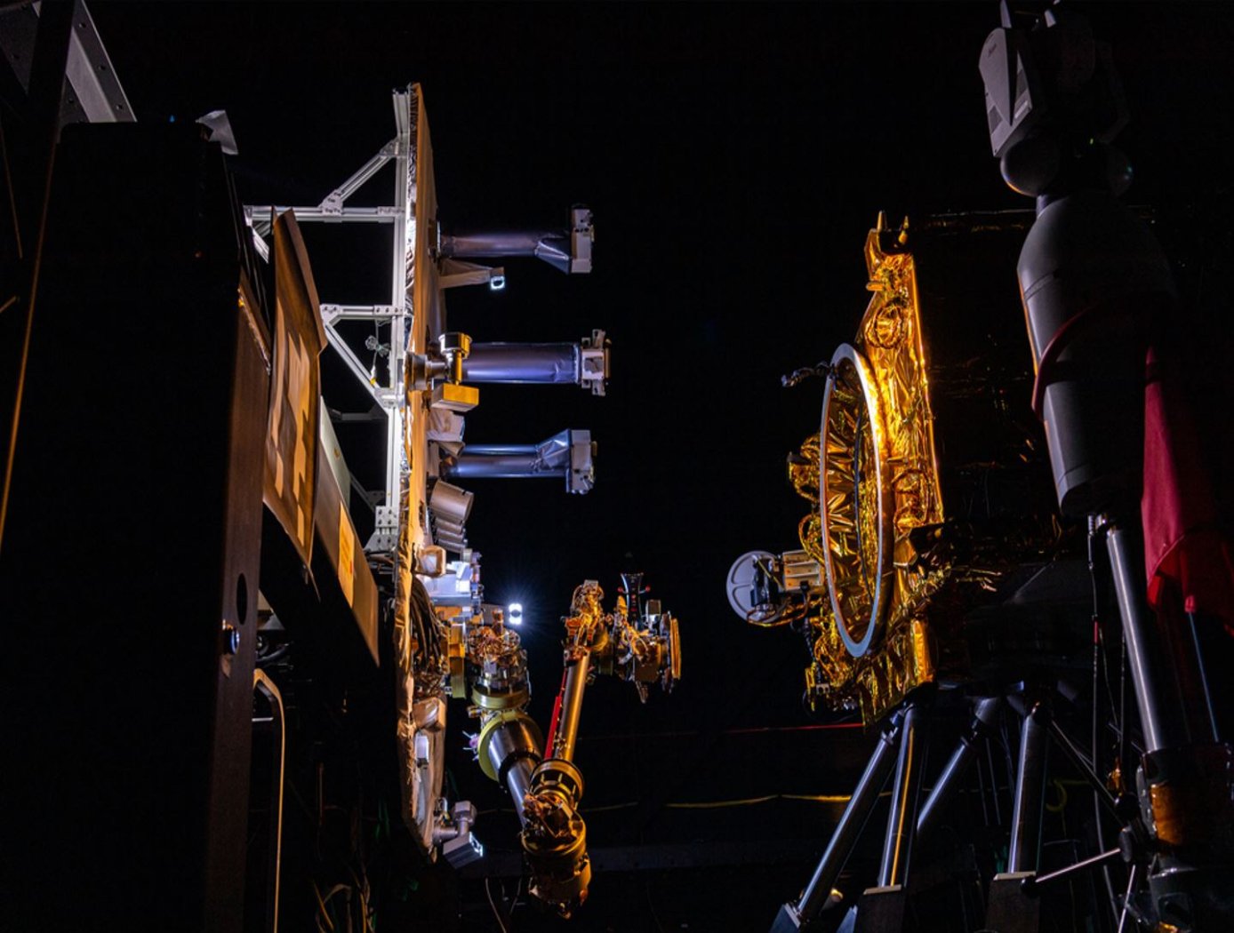
New motors for next-generation in-space servicing
Satellites and other spacecraft require maintenance and service after being deployed in orbit, requiring a wide variety of tools that perform multiple maintenance tasks (grip, cut, refuel, etc.). Current drive systems for the tool interfaces on the robotic arms that perform these service tasks are not as robust nor packaged properly for use in the ATDS. The ATDS is one part of a larger in-space servicing system (example shown in the figure below) that must be versatile and perform multiple jobs.
Here, innovators at the NASA Goddard Space Flight Center have developed new BLDC motors to provide the torque necessary to drive the wide variety of tools needed for in-space servicing. The four motors provide torque to the coupler drive, linear drive, inner rotary drive, and outer rotary drive of the ATDS. The new BLDC motors will enable the tools attached to the ATDS to be operated in multiple modes of operation.
Each of the four motors have been customized with different speed and torque capabilities to meet the different performance requirements of the various actuator drive trains while maintaining a common gearhead across all the motors. Further, the packaging surrounding the motors has been tailored to reduce the overall weight of the motors and reduce the motor footprint to meet the needs of the ATDS. The BLDC motors for the ATDS are available for patent licensing.
information technology and software
Space Traffic Management (STM) Architecture
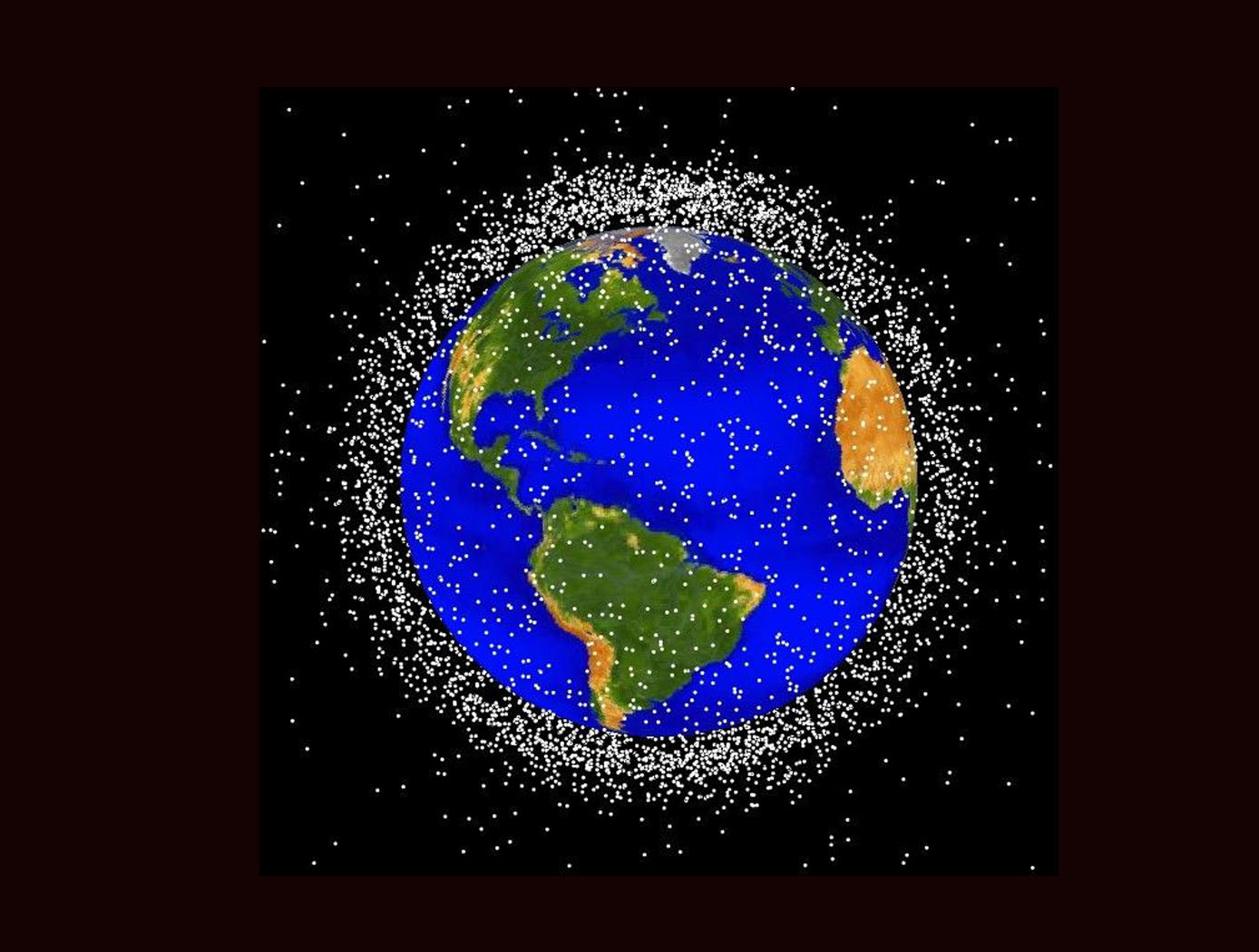
As ever larger numbers of spacecraft seek to make use of Earth's limited orbital volume in increasingly dense orbital regimes, greater coordination becomes necessary to ensure these spacecraft are able to operate safely while avoiding physical collisions, radio-frequency interference, and other hazards. While efforts to date have focused on improving Space Situational Awareness (SSA) and enabling operator to operator coordination, there is growing recognition that a broader system for Space Traffic Management (STM) is necessary. The STM architecture forms the framework for an STM ecosystem, which enables the addition of third parties that can identify and fill niches by providing new, useful services. By making the STM functions available as services, the architecture reduces the amount of expertise that must be available internally within a particular organization, thereby reducing the barriers to operating in space and providing participants with the information necessary to behave responsibly. Operational support for collision avoidance, separation, etc., is managed through a decentralized architecture, rather than via a single centralized government-administered system.
The STM system is based on the use of standardized Application Programming Interfaces (API) to allow easier interconnection and conceptual definition of roles to more easily allow suppliers with different capabilities to add value to the ecosystem. The architecture handles basic functions including registration, discovery, authentication of participants, and auditable tracking of data provenance and integrity. The technology is able to integrate data from multiple sources.
Aerospace
Spacecraft with Artificial Gravity Modules
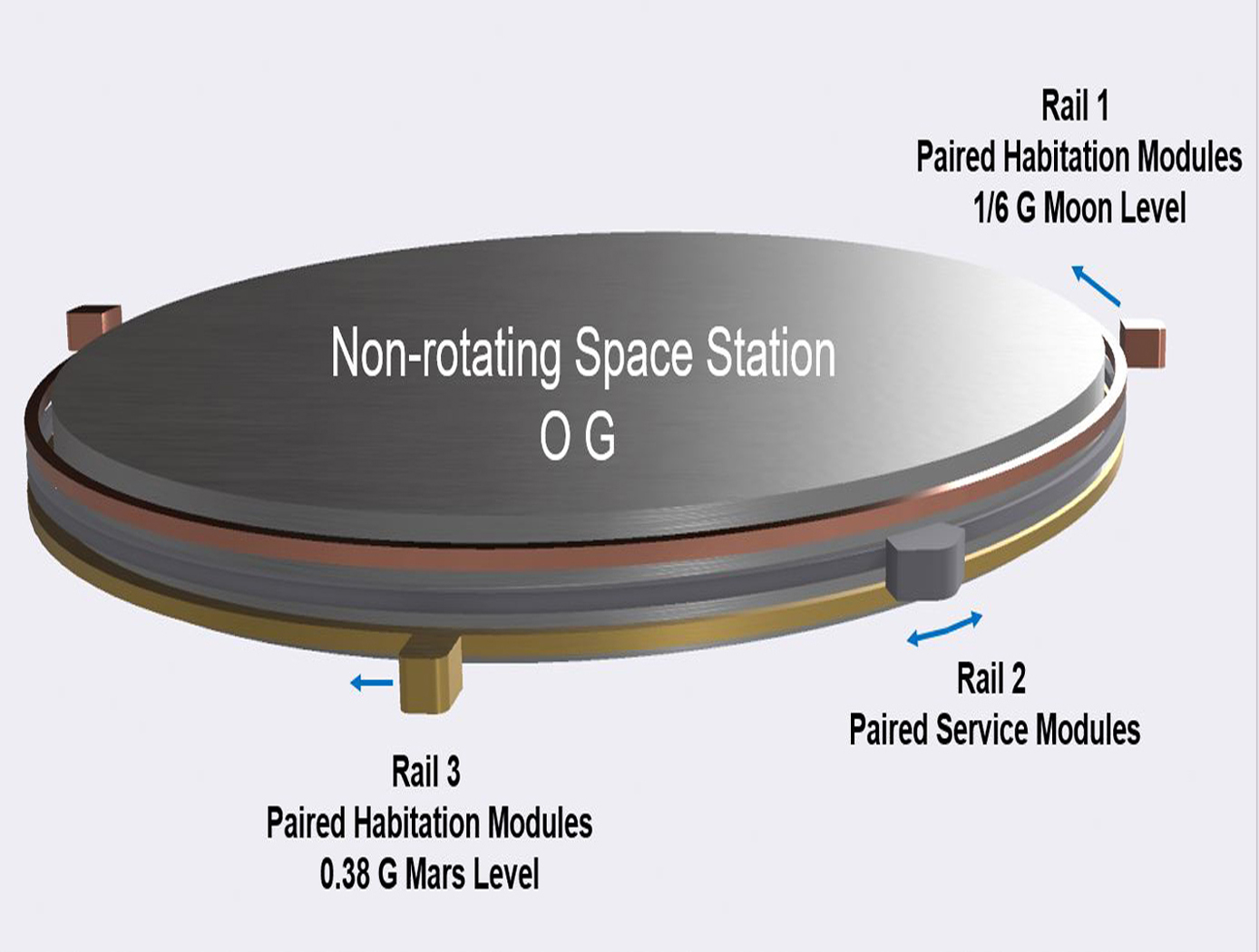
Conventionally, the approaches of creating artificial gravity in space was envisioned as a large rotating space station that creates an inertial force that mimics the effects of a gravitational force. However, generating artificial gravity with large rotating structures poses problems, including (1) the need to mass balance the entire rotating spacecraft in order to eliminate or minimize rotational imbalance causing gyroscopic precession/nutation motions and other oscillations of the rotating spacecraft; (2) the potentially prohibitive cost, time and schedule to build such a large rotating system; (3) the need to mass balance the spacecraft in real-time so as to minimize passenger discomfort and structural stress on the spacecraft; (4) the difficulty in docking other spacecraft to the rotating spacecraft; (5) the absence or minimal presence of non-rotating structure for 0G research and industrial use; and (6) the generation of extraneous Coriolis effect on spacecraft inhabitants. The novel technology can help solve the problems referenced above and other problems by (1) providing a non-rotating space station or structure, and connecting modules that generate artificial gravity by traveling along a circular path around the non-rotating space station; (2) providing modules that are more easily built and balanced; (3) providing a stationary structure that can provide a platform for other components that do not need gravity to function; (4) providing capability to actively interrogate what levels of mass imbalance are acceptable, for use in determining operational constraints; and (5) reducing or eliminating Coriolis effect on occupants in habitation modules. The concepts of the invention are very cost-effective and allow for building a minimal initial system to produce artificial gravity at the first phases of construction, before the full structure is built. An additional benefit is that construction and assembly of new capabilities can be performed without disrupting the ongoing artificial gravity environment of the existing structure.
Materials and Coatings
Novel Shape Memory Composite Substrate
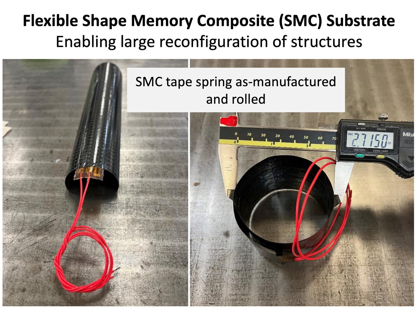
The new SMC substrate has four components: a shape memory polymer separately developed at NASA Langley; a stack of thin-ply carbon fiber sheets; a custom heater and heat spreader between the SMC layers; and integrated sensors (temperature and strain). The shape memory polymer allows the as-fabricated substrate to be programmed into a temporary shape through applied force and internal heating. In the programmed shape, the deformed structure is in a frozen state remaining dormant without external constraints. Upon heating once more, the substrate will return slowly (several to tens of seconds) to the original shape (shown below).
The thin carbon fiber laminate and in situ heating solve three major pitfalls of shape memory polymers: low actuation forces, low stiffness and strength limiting use as structural components, and relatively poor heat transfer. The key benefit of the technology is enabling efficient actuation and control of the structure while being a structural component in the load path. Once the SMC substrate is heated and releases its frozen strain energy to return to its original shape, it cools down and rigidizes into a standard polymer composite part. Entire structures can be fabricated from the SMC or it can be a component in the system used for moving between stowed and deployed states (example on the right). These capabilities enable many uses for the technology in-space and terrestrially.
manufacturing
Modular Artificial-Gravity Orbital Refinery Spacecraft
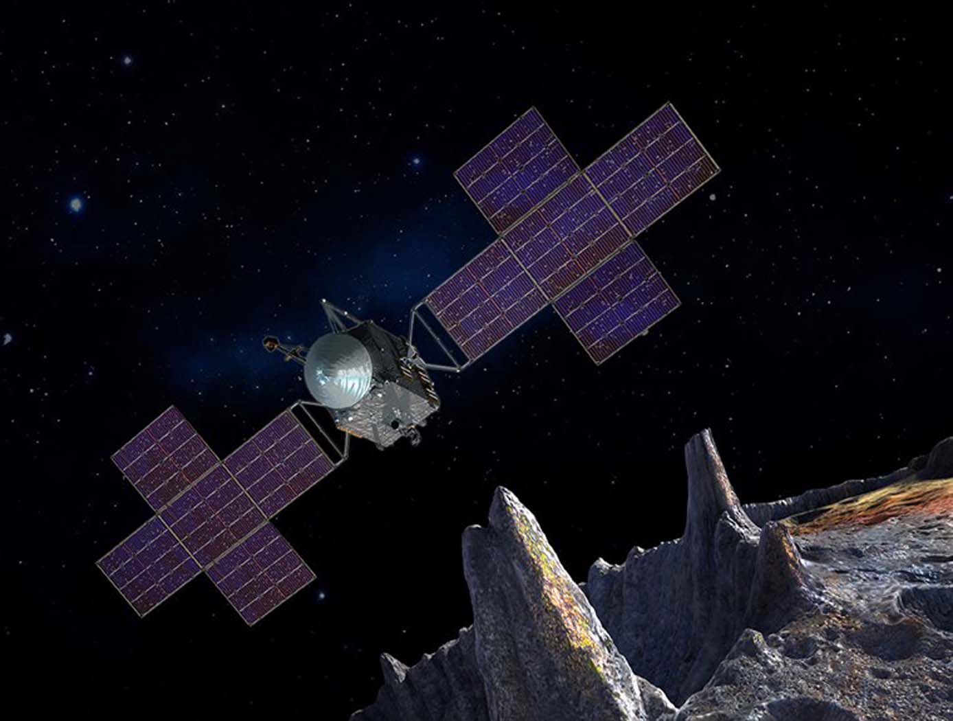
Modular Artificial-Gravity Orbital Refinery Spacecraft is a solution for refining in-situ materials collected in space, such as from asteroids and Mars moons, as well as recycling spacecraft debris, while orbiting in micro-gravity conditions. The spacecraft is coupled with refining modules for refining and recycling different types of materials. It generates artificial gravity for operation in low-gravity environments. The spacecraft is comprised of rotating rings, each generating artificial gravity and angular momentum. When the rotating rings are combined on the spacecraft platform, however, they have a net near-zero angular momentum such that the spacecraft can change its attitude with minimal propellant or rotate at the rate of the object the spacecraft platform is attached to. The spacecraft platform can self-balance to accommodate different sized modules and modules with moving loads. The refined and recycled materials can be used to create products in-situ as well as products too large to launch from Earth, such as construction of orbiting space habitats, large spacecraft, solar-power stations, and observatories.
communications
Cascaded Offset Optical Modulator
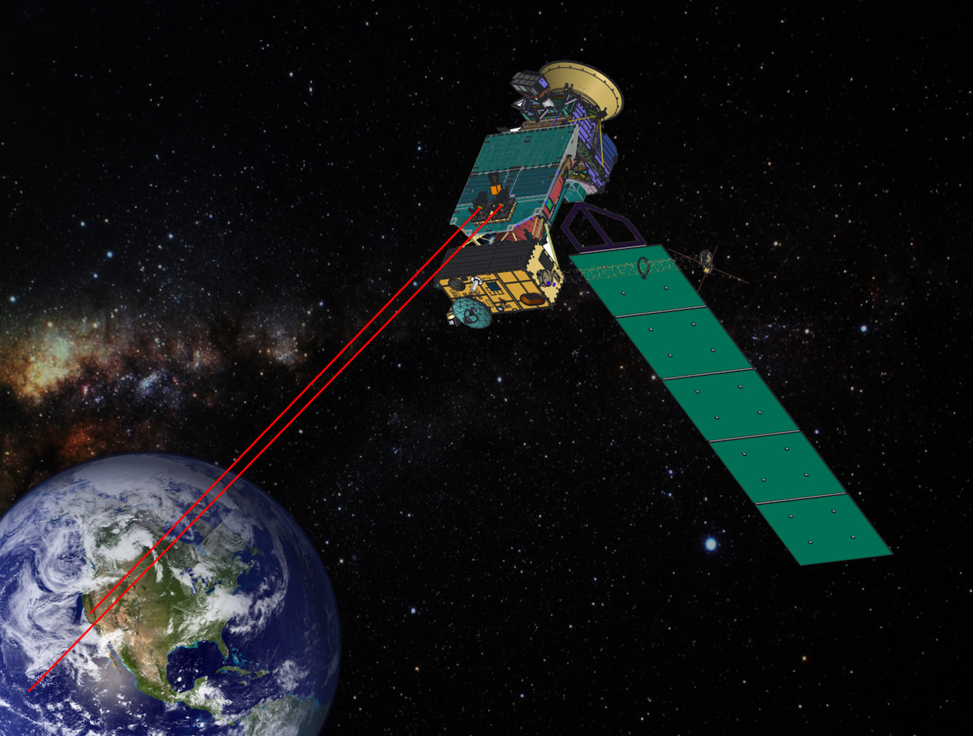
A unique challenge in the development of a deep space optical SDR transmitter is the optimization of the ER. For a Mars to Earth optical link, an ER of greater than 33 dB may be necessary. A high ER, however, can be difficult to achieve at the low Pulse Position Modulation (PPM) orders and narrow slot widths required for high data rates. The Cascaded Offset Optical Modulator architecture addresses this difficulty by reducing the width of the PPM pulse within the optical modulation subsystem, which relieves the SDR of the high signal quality requirements imposed by the use of an MZM. With the addition of a second MZM and a variable time delay, all of the non-idealities in the electrical signal can be compensated by slightly offsetting the modulation of the laser. The pulse output is only at maximum intensity during the overlap of the two MZMs. The width of the output pulse is effectively reduced by the offset between MZMs. Measurement and analysis of the system displayed, for a 1 nanosecond pulse width, extinction ratios of of 32.5 dB, 39.1 dB, 41.6 dB, 43.3 dB, 45.8 dB, and 48.2 dB for PPM orders of 4, 16, 32, 64, 128, and 256, respectively. This approach is not limited to deep space optical communications, but can be applied to any optical transmission system that requires high fidelity binary pulses without a complex component. The system could be used as a drop-in upgrade to many existing optical transmitters, not only in free space, but also in fiber. The system could also be implemented in different ways. With an increase in ER, the engineer has the choice of using the excess ER for channel capacity, or simplifying other parts of the system. The extra ER could be traded for reduced laser power, elimination of optical amplifiers, or decreased system complexity and efficiency.
Health Medicine and Biotechnology

In-Situ Resource Utilization (ISRU): Methylotrophic Microorganisms Expressing Soluble Methane Monooxygenase Proteins
Microorganisms are unique from the standpoint that they can be employed as self-replicating bio-factories to produce both native and engineered mission relevant bio-products. Methane (CH<sub>4</sub>) usage in In-Space Manufacturing (ISM) platforms has been discussed previously for human exploration and has been proposed to be used in physicochemical systems as a propulsion fuel, supply gas, and in fuel cells. Carbon Dioxide (CO<sub>2</sub>) is abundant on Mars and manned spacecraft. On the International Space Station (ISS), NASA reacts excess CO<sub>2</sub> with Hydrogen (H<sub>2</sub>) to generate CH<sub>4</sub> and Water (H<sub>2</sub>O) using the Sabatier System (Figure 1). The resulting water is recovered in the ISS, but the methane is vented to space. Recapturing this methane and using it for microbial manufacturing could provide a unique approach in development of in-space bio-manufacturing. Thus, there is a capability need for systems that convert methane into valuable materials. Methane (CH<sub>4</sub>) is a potential carbon substrate for methanotrophic microorganisms which are able to metabolize CH<sub>4</sub> into biomass. The innovative technology from NASA Ames Research Center ports Soluble Methane Monooxygenase (sMMO) to <i>Pichia</i>, that is, it moves the methane metabolism into a robust microbial factory (<i>Pichia pastoris</i>) (Figure 2). The yeast <i>Pichia pastoris</i> is a refined microbial factory that is used widely by industry because it efficiently secretes products. <i>Pichia</i> could produce a variety of useful products in space. <i>Pichia</i> does not consume methane but robustly consumes methanol, which is one enzymatic step removed from methane. This novel innovation engineers <i>Pichia</i> to consume methane thereby creating a powerful methane-consuming microbial factory and utilizing methane in a robust and flexible synthetic biology platform.
Communications

Boosting Quantum Communication Efficiency
The technology consists of an array of quantum photon sources connected via a sophisticated switching network. This system is designed to produce single pairs of entangled photons at a high rate while actively suppressing the generation of multiple pairs. The key innovation lies in its ability to detect and eliminate instances where two or more entangled photon pairs are generated, effectively reducing noise in the quantum system.
The technology operates by providing a heralding pulse that notifies the external system of successful entangled photon generation. When multiple pairs are detected, they are prevented from entering the rest of the system, thereby maintaining the integrity of the quantum information.
By combining multiple single-photon sources through its switching network, the technology not only reduces noise but also increases the overall single photon pair generation rate. This dual approach of noise reduction and increased generation efficiency improves qubit transmission rates, potentially by a factor of 10 to 100 over current methods.
While still in the early stages of development, the source array represents a significant advancement in quantum communication systems. It addresses the critical need for high-fidelity entangled photon sources, which are essential for various quantum applications, including entangling sensor networks, quantum computer networks, and quantum key distribution for secure communications.
As quantum technologies continue to evolve, this source array technology positions itself as a crucial component in the development of large-scale, efficient quantum networks, offering a solution to one of the fundamental challenges in quantum information transmission.
Materials and Coatings

Advanced AlF3-Passivated Aluminum Mirrors
NASA’s innovative passivation process consists of exposing in-situ Physical Vapor Deposited oxide-free AI samples in a high or ultra-high vacuum chamber at ambient temperature to a low-pressure reactive gas of xenon difluoride (XeF2) immediately after depositing the AI layer. In this chemisorption process, the XeF2 is adsorbed on the surface of the AI layer, and due to the affinity of Al to fluorine molecules, the weakly-bound Xe dissociates and is pumped out of the chamber. A thin AlF3 overcoat layer is produced as a result.
Other embodiments of the invention include the use of alternative processing gasses for the passivation treatment, or the utilization of a plasma source to increase the ion/atom ratio of the incident fluorine species resulting after XeF2 dissociation. Similarly, different mirror substrates materials with suitable surface characteristics in the FUV could be employed.
In addition to the improved FUV reflectance, environmental stability, and maintained efficiency at higher wavelengths of the resulting Al mirrors, this NASA process has several unique features. Firstly, the entire process is carried out at ambient temperature, eliminating the need for high-temperature fluoride deposition. Secondly, the process is highly scalable, limited only by the size of the coating chamber where the passivation of XeF2 is carried out. Finally, the process can be manipulated to conform to any geometry, enabling its use for curved optics.
While NASA originally developed the passivation of oxide-free aluminum coatings to realize reflectivity enhancement in the Far-Ultraviolet for the Large UV/Optical/IR Surveyor (LUVOIR), it may also be useful to companies that manufacture ground-based or space-based optical systems with sensitivity to the FUV spectrum. Examples include optics for space telescopes with reflective elements, vacuum-ultraviolet (VUV) plasma analysis tools, photolithography instrumentation, and wafer inspection tools.
Manufacturing

Ultra-low Reflectivity Black Silicon Pupil Masks
Fabrication of NASA's pupil mask begins with the preparation of a silicon wafer, which serves as the foundation for the black silicon structure. The wafer undergoes ion beam figuring (IBF), a non-contact technique that precisely removes surface irregularities at the nanometer scale. This process ensures that the silicon surface is diffraction-limited, eliminating errors that could degrade optical performance. Once the wafer is polished to the required precision, it is then processed lithographically to define the mask pattern, creating reflective and absorptive regions essential for controlling light propagation.
To achieve the desired high absorption characteristics, the lithographically patterned wafer undergoes cryogenic etching, a sophisticated process that transforms the silicon surface into a highly textured, black silicon structure. This method utilizes a controlled plasma environment with sulfur hexafluoride (SF6) and oxygen to etch the surface at cryogenic temperatures. The process is carefully optimized by adjusting parameters such as gas flow rates, chamber pressure, ion density, and etch duration, leading to the formation of high-aspect-ratio nanostructures on the silicon substrate. These structures, resembling a dense “forest” of silicon nanospikes, trap and diffuse incoming light, drastically reducing specular reflection. The resulting surface exhibits an ultra-low reflectivity that is orders of magnitude lower than conventional polished silicon.
By leveraging NASA’s cutting-edge fabrication technique, the newly developed black silicon pupil mask offers a powerful solution for high-contrast astronomical imaging. Its ability to minimize scattered light and enhance optical contrast makes it an ideal component for space telescopes tasked with directly imaging exoplanets as well as other applications requiring ultra low reflectivity systems.


