Directional UAV Localization of Power Line Ultraviolet Corona
sensors
Directional UAV Localization of Power Line Ultraviolet Corona (LAR-TOPS-228)
Improved method of detecting power line faults
Overview
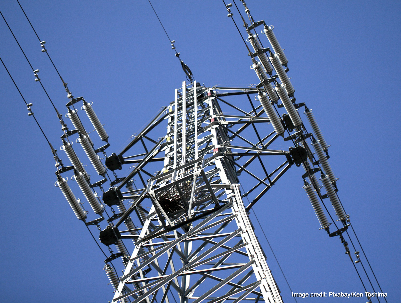
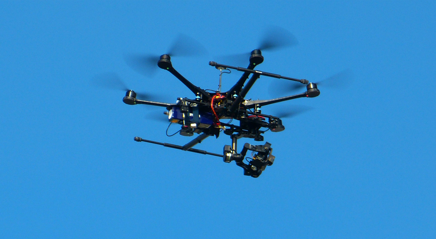
NASA's Langley Research Center has developed a novel system that uses an ultra-violet camera to detect, inspect, and analyze a corona discharge. This discharge signifies a power line fault, making the technology ideal for use in power line inspections. When coupled to a drone, the technology offers the ability to remotely monitor power lines in a cost effective way. Adding GPS technology results in precise location of power line faults.
The Technology
This technology comprises a novel system of detecting, inspecting and analyzing a corona discharge using an ultra-violet camera. It is useful for a number of potential applications, most notably, power line fault detection. The most novel feature is that it uses UV instead of IR which has been problematical for corona discharge detection because there is too much interference from other sources. UV detection offers images that isolate the location of the corona discharge with far greater precision.


Benefits
- Easily used with drones and combined with GPS for precise location of faults
- Libraries of typical UV images of corona discharges by component type (i.e. insulator vs conductor) can be added to the firmware to provide additional inspection capabilities
- Inexpensive
Applications
- Power transmission line inspection and fault detection
- Electric rail applications
- Trolley maintenance
- Wildfire detection and location
Similar Results

Powerline Geolocation
The electrical transmission lines used to transmit power are optimized for 50 to 60 Hz waveforms, but are suitable for waveforms of higher frequencies, into the megahertz range. Therefore, powerline conductors are capable of transmitting signals which could be used for geolocation.
Indeed, frequencies in the 100 kHz range are used for diagnostic purposes in contemporary power grids today. Signals transmitted in this band are used to verify the operation of sites along the power grid, are used to configure the power grid (for example, throw a circuit breaker).
The technology takes advantage of the suitability of electrical conductors employed in power transmission for signal transmission in the sub-megahertz range, and, in the preferred embodiment, utilizes the existing diagnostics signals in this range for geolocation.

Low Frequency Portable Acoustic Measurement System
Langley has developed various technologies to enable the portable detection system, including:
- 3-inch electret condenser microphone - unprecedented sensitivity of -45 dB/Hz
- compact nonporous windscreen - suitable for replacing spatially demanding soaker hoses in current use
- infrasonic calibrator for field use - piston phone with a test signal of 110 dB at 14Hz.
- laboratory calibration apparatus - to very low frequencies
- vacuum isolation vessel - sufficiently anechoic to permit measurement of background noise in microphones at frequencies down to a few Hz
- mobile source for reference - a Helmholtz resonator that provides pure tone at 19 Hz
The NASA system uses a three-element array in the field to locate sources of infrasound and their direction. This information has been correlated with PIREPs available in real time via the Internet, with 10 examples of good correlation.

In Situ Wire Damage Detection and Rerouting System
The tester was designed to monitor electrical faults in either online or offline modes of operation. In the online mode, wires are monitored without disturbing their normal operation. A cable can be monitored several times per second in the offline mode, and once per second in the online mode. The online cable fault locator not only detects the occurrence of a fault, but also determines the type of fault (short/open/intermittent) and the location of the fault. This enables the detection of intermittent faults that can be repaired before they become serious problems. Since intermittent faults occur mainly during operations, a built-in memory device stores all relevant fault data. This data can be displayed in real time or retrieved later so maintenance and repairs can be completed without spending countless hours attempting to pinpoint the source of the problem.
Hardware and algorithms have also been developed to safely, efficiently, and autonomously transfer electrical power and data connectivity from an identified damaged/defective wire in a cable to an alternate wire path. This portion of the system consists of master and slave units that provide the diagnostic and rerouting capabilities. A test pulse generated by the master unit is sent down an active wire being monitored by the slave unit. When the slave unit detects the test pulse, it routes the pulse back to the master unit through a communication wire. When the master unit determines that a test pulse is not being returned, it designates that wire as faulty and reroutes the circuit to a spare wire.

Low Weight Flight Controller Design
Increasing demand for smaller UAVs (e.g., sometimes with wingspans on the order of six inches and weighing less than one pound) generated a need for much smaller flight and sensing equipment. NASA Langley's new sensing and flight control system for small UAVs includes both an active flight control board and an avionics sensor board. Together, these compare the status of the UAVs position, heading, and orientation with the pre-programmed data to determine and apply the flight control inputs needed to maintain the desired course.
To satisfy the small form-factor system requirements, micro-electro-mechanical systems (MEMS) are used to realize the various flight control sensing devices. MEMS-based devices are commercially available single-chip devices that lend themselves to easy integration onto a circuit board. The system uses less energy than current systems, allowing solar panels planted on the vehicle to generate the systems power. While the lightweight technology was designed for smaller UAVs, the sensors could be distributed throughout larger UAVs, depending on the application.

Self-Adjusting Gap System for Charge Mitigation and Monitoring
Fixed-point or spark-plug discharge systems are challenging to set up and maintain, often suffering from performance degradation or failure as repeated discharges damage and alter contact points. Similarly, contact-based solutions like slip rings can introduce torque drag and create contamination particles over time as materials wear down. The SAG system eliminates these problems with its innovative contactless design, proven to cycle reliably tens of thousands of times without failure. In testing, this system survived approximately 25,000 times the expected mission charge cycles.
The SAG system consists of a flexure, discharge point, and bleed circuit that controls the voltage, location and current at which a discharge occurs. The flexure is electrically isolated from the rest of the stationary body forcing the discharge current to go through the bleed circuit. This provides the ability to protect sensitive electronics from a sudden field collapse or ground plane disturbance. The flexure is able of taking different forms depending on the application and desired characteristics allowing for a scalable system, modifiable for various mission parameters. Additionally, the SAG system is passive until needed, requiring no active electronics unless used as a sensor. Due to its contactless nature, the SAG system simplifies live wear testing, significantly lowering costs compared to traditional mechanisms. Unlike fixed-point systems, it does not require precise dynamic clearances, making it more tolerant to launch loads and reducing the severity of electrical discharge events.
Although designed for space and planetary exploration applications, the SAG system may also be valuable for terrestrial use cases for monitoring charging of electrically isolated components where charge buildup may occur or where grounding isn’t possible. The SAG System is at technology readiness level (TRL) 6 (system demonstration in relevant environment) and is available for patent licensing.


