Fingerprinting for Rapid Battery Inspection
Optics
Fingerprinting for Rapid Battery Inspection (LAR-TOPS-378)
Time-saving approach to enable battery dendrite detection
Overview
Dendrite growth in lithium-ion batteries can lead to fires and explosions, limiting battery life and safety. High resolution radiographs can be used to detect subtle precursors to battery failure, but it can be tedious to collect and combine these radiographs over the course of testing many battery samples.
NASA researchers developed a novel technique for creating unique orientation fingerprints on battery samples prior to digital radiograph collection. The fingerprints enable rapid assembly of high-resolution images. This allows efficient inspection of batteries for early signs of dendrite formation, improving safety and extending useful battery life. This technology can improve efficiency in battery R&D, battery production, and other electronics applications.
The Technology
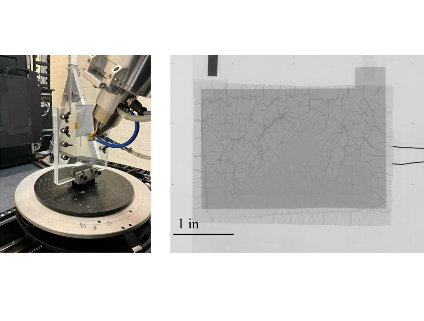
The technology utilizes photopolymer droplets (invisible to the digital radiograph) with embedded radiopaque fragments to create randomized fingerprints on battery samples. The droplets are deposited using a jig (see figure on right) that precisely positions samples. Then, at different points during battery R&D testing or use, digital radiography imaging with micron-level resolution can be performed.
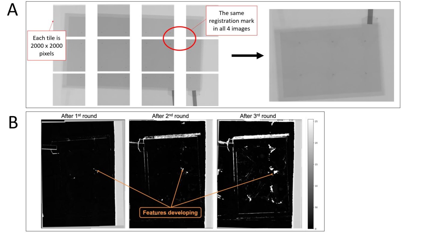
The high-resolution imaging required to detect dendrite formation requires images to be collected in multiple “tiles” as shown below. The randomized fingerprints uniquely identify relative positioning of these tiles, allowing rapid assembly of composite high-resolution images from multiple tiles.
This same composite creation process can be used for images taken at a series of points in time during testing, and background subtraction can be applied to efficiently compare how the battery is changing over successive charge/discharge cycles to identify dendrite formation. This inspection technique is proven effective for thin-film pouch cell prototypes at NASA, and it works well at the lowest available x-ray energy level (limiting impact on the samples). The Fingerprinting for Rapid Battery Inspection technology is available for patent licensing.


Benefits
- Improve battery designs to increase safety: Enables detection of dendrite formation, enabling battery design to better mitigate battery failure
- Efficient battery R&D: Assembles image mosaics nearly automatically (~5-minutes), drastically saving time compared to repeatedly manually stitching ~20 high-res image tiles over successive tests
- Low-energy dosing: As the technology works at the low operating limit of radiography equipment, the risk of negative impact of x-rays on the underlying materials is low
- Streamlined production quality control: Implemented at scale, the technology can support detection of folds or tears in separator material viewable via radiography
Applications
- Battery R&D: Accelerate evaluation of cell chemistries and constructions
- Battery Production: Enable high-throughput quality inspection during manufacturing
- Battery field monitoring: facilitate assessment of battery health after deployment
- Electronics manufacturing: Adaptable to inspection of components like semiconductors or composites requiring high resolution and throughput inspection
Technology Details
Optics
LAR-TOPS-378
LAR-20275-1
Automated registration of multi-mode nondestructive evaluation data. Spaeth, et al. 2023.
https://ntrs.nasa.gov/citations/20230001996
|
Tags:
|
Similar Results

Battery Management System
The technology is comprised of a simple and reliable circuit that detects a single bad cell within a battery pack of hundreds of cells and it can monitor and balance the charge of individual cells in series. NASA's BMS is cost effective and can enhance safety and extend the life of critical battery systems, including high-voltage Li-ion batteries that are used in electric vehicles and other next-generation renewable energy applications.
The BMS uses saturating transformers in a matrix arrangement to monitor cell voltage and balance the charge of individual battery cells that are in series within a battery string. The system includes a monitoring array and a voltage sensing and balancing system that integrates simply and efficiently with the battery cell array, limiting the number of pins and the complexity of circuitry in the battery. The arrangement has inherent galvanic isolation, low cell leakage currents, and allows a single bad or imbalanced cell in a series of several hundred to be identified. Cell balancing in multi-cell battery strings compensates for weaker cells by equalizing the charge on all the cells in the chain, thus extending battery life. Voltage sensing helps avoid damage from over-voltage that can occur during charging and from under-voltage that can occur through excessive discharging.

Internal Short Circuit Testing Device to Improve Battery Designs
Astronauts' lives depend on the safe performance and reliability of lithium-ion (Li-ion) batteries when they are working and living on the International Space Station. These batteries are used to power everything such as communications systems, laptop computers, and breathing devices. Their reliance on safe use of Li-ion batteries led to the research and development of a new device that can more precisely trigger internal short circuits, predict reactions, and establish safeguards through the design of the battery cells and packs. Commercial applications for this device exist as well, as millions of cell phones, laptops, and electronic drive vehicles use Li-ion batteries every day. In helping manufacturers understand why and how Li-ion batteries overheat, this technology improves testing and quality control processes.
The uniqueness of this device can be attributed to its simplicity. In a particular embodiment, it is comprised of a small copper and aluminum disc, a copper puck, polyethylene or polypropylene separator, and a layer of wax as thin as the diameter of one human hair. After implantation of the device in a cell, an internal short circuit is induced by exposing the cell to higher temperatures and melting the wax, which is then wicked away by the separator, cathode, and anode, leaving the remaining metal components to come into contact and induce an internal short. Sensors record the cell's reactions. Testing the battery response to the induced internal short provides a 100% reliable testing method to safely test battery containment designs for thermal runaway.
This jointly developed and patented technology is available for your company to license and develop into a commercial product. NASA does not manufacture products for commercial sale.

Li-ion Cell Calorimeter
Li-ion batteries are an integral part of energy storage systems used in NASA's Exploration program, as well as many modern terrestrial industries. Innovators at the NASA Johnson Space Center wanted a better way to measure total and fractional heat response of specific types of Li-ion cells when driven into a thermal runaway condition. They developed a calorimeter with at least two chambers, one for the battery cell under test and at least one other chamber for receiving the thermal runaway ejecta debris. Both are designed to be structurally strong and thermally insulated. When the test cell is intentionally driven into thermal runaway, ejecta explodes into the ejecta chamber and is decelerated and collected. Thermal sensors are strategically placed throughout the chambers to collect thermal data during the test. Customized software analyzes the thermal data and determines key calorimeter parameters with a high degree of accuracy.

Portable Microscope
The handheld digital microscope features a 3D-printed chassis to house its hardware, firmware, and rechargeable Li-ion battery with built-in power management. It incorporates an internal stainless-steel cage system to enclose and provide mechanical rigidity for the optics and imaging sensor. To reduce the microscope’s size, yet retain high spatial resolution, engineers devised an optical light path that uniquely folds back on itself using high reflectivity mirrors, thus significantly reducing internal volume.
Imaging control and acquisition is performed using a secure web-based graphical user interface accessible via any wireless enabled device. The microscope serves as its own wireless access point thus obviating the need for a pre-existing network. This web interface enables multiple simultaneous connections and facilitates data sharing with clinicians, scientists, or other personnel as needed. Acquired images can be stored locally on the microscope server or on a removable SD card. Data can be securely downloaded to other devices using a range of industry standard protocols.
Although the handheld digital microscope was originally developed for in-flight medical diagnosis in microgravity applications, prototypes were thoroughly ground-tested in a variety of environments to verify the accurate resolve of microbial samples for identification and compo-sitional analysis for terrestrial field use. Owing to its portability, other applications demanding rapid results may include research, education, veterinarian, military, contagion disaster response, telemedicine, and point-of-care medicine.
MMOD Impact Detection and Location
Multiple strain sensors encoded into one or more optical fibers are affixed to a MMOD shield or structure. The optical fiber(s) is/are connected to a data collection device that records strain data at a frequency sufficient to resolve MMOD impact events. Strain data are processed and presented on a computer display. MMOD impact imparts a transient shock loading to a structure which is manifested as transient strain as the shock wave moves through the structure. MMOD impacts are determined from the time signature of, both, measured strain from multiple sensors on the optical fiber(s) as well as strain resulting from plastic strain induced in the MMOD shield and structure as a consequence of the MMOD impact (for materials exhibiting plastic strain). The array of strain sensors, encoded into one or more optical fibers using Fiber Bragg Grating (FBG) technology, records time varying strain to identify that a strike has occurred and at what time it occurred. Strike location information can be inferred from the residual plastic strain recorded by the multitude of strain sensors in the fiber(s). One or more optical fibers may be used to provide optimal coverage of the area of interest and/or to ensure a sufficient number of strain measurements are provided to accurately characterize the nature of the impact.


