Computational Visual Servo
information technology and software
Computational Visual Servo (LAR-TOPS-61)
Automatic measurement and control for smart image enhancement
Overview
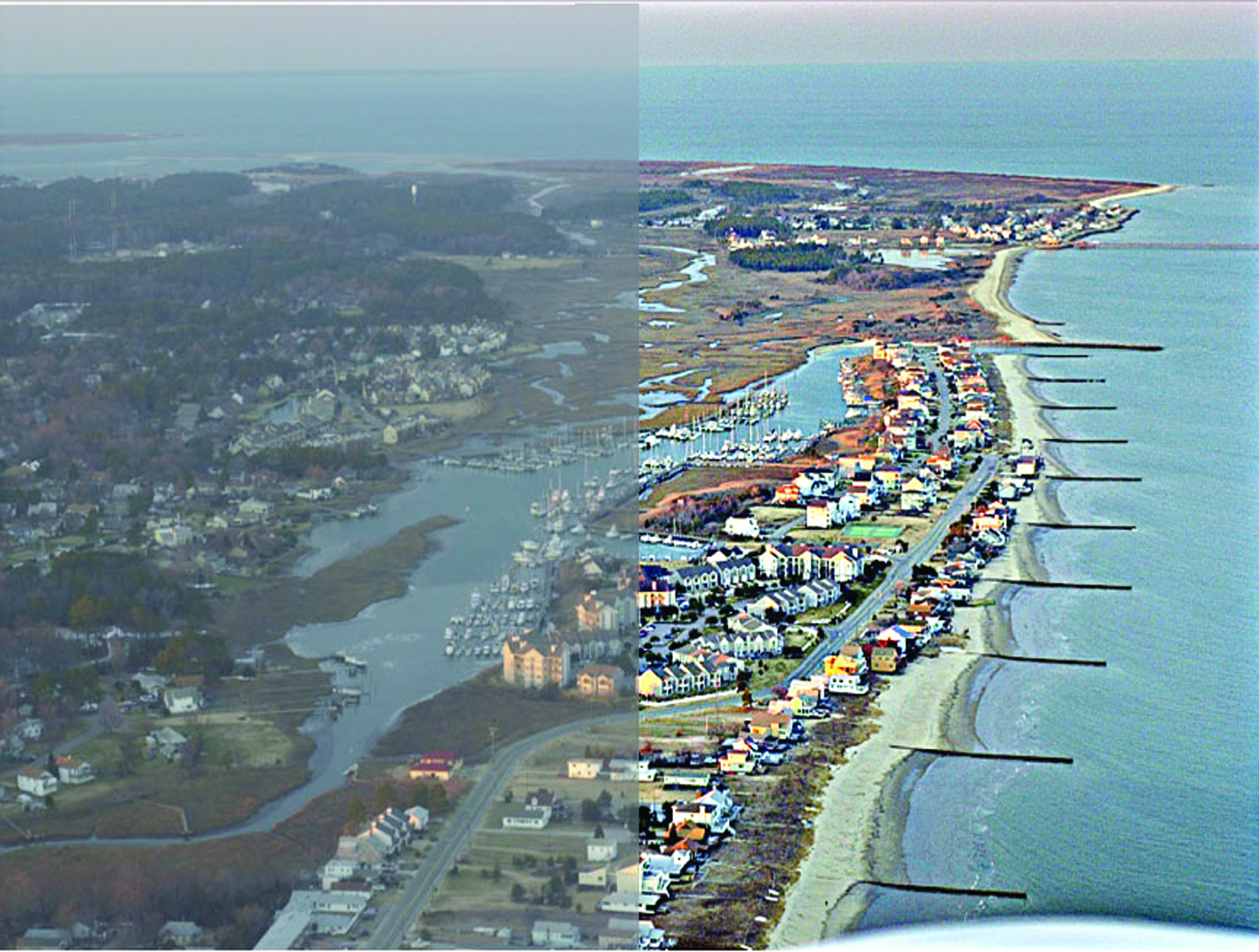
NASA's Langley Research Center researchers have developed an automatic measurement and control method for smart image enhancement. Pilots, doctors, and photographers will benefit from this innovation that offers a new approach to image processing. Initial advantages will be seen in improved
medical imaging and nighttime photography. Standard image enhancement software is unable to improve poor quality conditions such as low light, poor clarity, and fog-like conditions. The technology consists of a set of comprehensive methods that perform well across a wide range of conditions encountered in arbitrary images. Conditions include large variations in lighting, scene characteristics, and atmospheric (or underwater) turbidity variations. NASA is seeking market insights on commercialization of this new technology, and welcomes interest from potential producers, users, and licensees.
The Technology
The innovation improves upon the performance of passive automatic enhancement of digital images. Specifically, the image enhancement process is improved in terms of resulting contrast, lightness, and sharpness over the prior art of automatic processing methods. The innovation brings the technique of active measurement and control to bear upon the basic problem of enhancing the digital image by defining absolute measures of visual contrast, lightness, and sharpness. This is accomplished by automatically applying the type and degree of enhancement needed based on automated image analysis.
The foundation of the processing scheme is the flow of digital images through a feedback loop whose stages include visual measurement computation and servo-controlled enhancement effect. The cycle is repeated until the servo achieves acceptable scores for the visual measures or reaches a decision that it has enhanced as much as is possible or advantageous. The servo-control will bypass images that it determines need no enhancement.
The system determines experimentally how much absolute degrees of sharpening can be applied before encountering detrimental sharpening artifacts. The latter decisions are stop decisions that are controlled by further contrast or light enhancement, producing unacceptable levels of saturation, signal clipping, and sharpness.
The invention was developed to provide completely new capabilities for exceeding pilot visual performance by clarifying turbid, low-light level, and extremely hazy images automatically for pilot view on heads-up or heads-down display during critical flight maneuvers.


Benefits
- Systematic improvements in contrast, light, and sharpness
- Compatible with varied imaging technology
- Correction for both overexposure and underexposure
- Dusk and fog image resolution
Applications
- Photography - expanded enhancement capabilities
- Aviation - improved pilot visibility
- Automobile - improved driver visibility
- Video - Real-time digital enhancement
- Medical imaging - X-rays, computed tomography (CT), and magnetic resonance imaging (MRI)
- Surveillance - thermal and night vision
- Military - enhanced pilot vision and targeting
Similar Results

Reflection-Reducing Imaging System for Machine Vision Applications
NASAs imaging system is comprised of a small CMOS camera fitted with a C-mount lens affixed to a 3D-printed mount. Light from the high-intensity LED is passed through a lens that both diffuses and collimates the LED output, and this light is coupled onto the cameras optical axis using a 50:50 beam-splitting prism.
Use of the collimating/diffusing lens to condition the LED output provides for an illumination source that is of similar diameter to the cameras imaging lens. This is the feature that reduces or eliminates shadows that would otherwise be projected onto the subject plane as a result of refractive index variations in the imaged volume. By coupling the light from the LED unit onto the cameras optical axis, reflections from windows which are often present in wind tunnel facilities to allow for direct views of a test section can be minimized or eliminated when the camera is placed at a small angle of incidence relative to the windows surface. This effect is demonstrated in the image on the bottom left of the page.
Eight imaging systems were fabricated and used for capturing background oriented schlieren (BOS) measurements of flow from a heat gun in the 11-by-11-foot test section of the NASA Ames Unitary Plan Wind Tunnel (see test setup on right). Two additional camera systems (not pictured) captured photogrammetry measurements.

Strobing to Mitigate Vibration for Display Legibility
The dominant frequency of the vibration that requires mitigation can be known in advance, measured in real time, or predicted with simulation algorithms. That frequency (or a lower frequency multiplier) is then used to drive the strobing rate of the illumination source. For example, if the vibration frequency is 20 Hz, one could employ a strobe rate of 1, 2, 4, 5, 10, or 20 Hz, depending on which rate the operator finds the least intrusive. The strobed illumination source can be internal or external to the display.
Perceptual psychologists have long understood that strobed illumination can freeze moving objects in the visual field. This effect can be used for artistic effect or for technical applications. The present innovation is instead applicable for environments in which the human observer rather than just the viewed object undergoes vibration. Such environments include space, air, land, and sea vehicles, or on foot (e.g., walking or running on the ground or treadmills). The technology itself can be integrated into handheld and fixed display panels, head-mounted displays, and cabin illumination for viewing printed materials.

Super Resolution 3D Flash LIDAR
This suite of technologies includes a method, algorithms, and computer processing techniques to provide for image photometric correction and resolution enhancement at video rates (30 frames per second). This 3D (2D spatial and range) resolution enhancement uses the spatial and range information contained in each image frame, in conjunction with a sequence of overlapping or persistent images, to simultaneously enhance the spatial resolution and range and photometric accuracies. In other words, the technologies allows for generating an elevation (3D) map of a targeted area (e.g., terrain) with much enhanced resolution by blending consecutive camera image frames. The degree of image resolution enhancement increases with the number of acquired frames.

Fluid Lensing System for Imaging Underwater Environments
Fluid lensing exploits optofluidic lensing effects in two-fluid interfaces. When used in such interfaces, like air and water, coupled with computational imaging and a unique computer vision-processing pipeline, it not only removes strong optical distortions along the line of sight, but also significantly enhances the angular resolution and signal-to-noise ratio of an otherwise underpowered optical system. As high-frame-rate multi-spectral data are captured, fluid lensing software processes the data onboard and outputs a distortion-free 3D image of the benthic surface. This includes accounting for the way an object can look magnified or appear smaller than usual, depending on the shape of the wave passing over it, and for the increased brightness caused by caustics. By running complex calculations, the algorithm at the heart of fluid lensing technology is largely able to correct for these troublesome effects. The process introduces a fluid distortion characterization methodology, caustic bathymetry concepts, Fluid Lensing Lenslet Homography technique, and a 3D Airborne Fluid Lensing Algorithm as novel approaches for characterizing the aquatic surface wave field, modeling bathymetry using caustic phenomena, and robust high-resolution aquatic remote sensing. The formation of caustics by refractive lenslets is an important concept in the fluid lensing algorithm. The use of fluid lensing technology on drones is a novel means for 3D imaging of aquatic ecosystems from above the water's surface at the centimeter scale. Fluid lensing data are captured from low-altitude, cost-effective electric drones to achieve multi-spectral imagery and bathymetry models at the centimeter scale over regional areas. In addition, this breakthrough technology is developed for future in-space validation for remote sensing of shallow marine ecosystems from Low Earth Orbit (LEO). NASA's FluidCam instrument, developed for airborne and spaceborne remote sensing of aquatic systems, is a high-performance multi-spectral computational camera using Fluid lensing. The space-capable FluidCam instrument is robust and sturdy enough to collect data while mounted on an aircraft (including drones) over water.

Low Weight Flight Controller Design
Increasing demand for smaller UAVs (e.g., sometimes with wingspans on the order of six inches and weighing less than one pound) generated a need for much smaller flight and sensing equipment. NASA Langley's new sensing and flight control system for small UAVs includes both an active flight control board and an avionics sensor board. Together, these compare the status of the UAVs position, heading, and orientation with the pre-programmed data to determine and apply the flight control inputs needed to maintain the desired course.
To satisfy the small form-factor system requirements, micro-electro-mechanical systems (MEMS) are used to realize the various flight control sensing devices. MEMS-based devices are commercially available single-chip devices that lend themselves to easy integration onto a circuit board. The system uses less energy than current systems, allowing solar panels planted on the vehicle to generate the systems power. While the lightweight technology was designed for smaller UAVs, the sensors could be distributed throughout larger UAVs, depending on the application.


