Handheld Metal Tube Straightener
mechanical and fluid systems
Handheld Metal Tube Straightener (MSC-TOPS-107)
Tool removes bends from challenging tube-ends
Overview
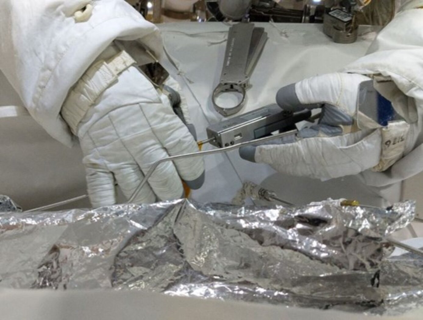
Researchers at NASA Johnson Space Center have developed the Handheld Metal Tube Straightener designed to remove bends within 3.5 inches of a tube end. The tool straightens thin, malleable 4mm metal tubes like those used for fuel, pneumatic or hydraulic pressurized lines. Commercially available tube straighteners use rollers to straighten long metal tubing, but the spacing of the rollers typically prevent or complicate bend-removal near the end of the tube and can also leave linear scratches on the straightened area. The handheld tube straightener can remove small and large bends near and at the tip of a tube so that it can be swaged into any commercial swage fitting. The Handheld Metal Tube Straightener was successfully used during a spacewalk on NASA's "EVA 61 Alpha Magnetic Spectrometer (AMS)" repair mission.
The Technology
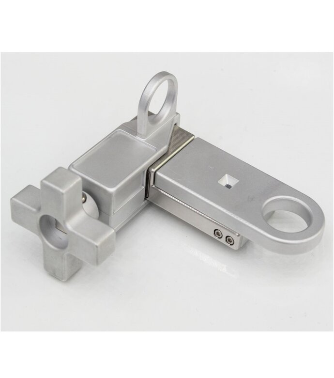
NASAs Handheld Metal Tube Straightener is built with a stationary anvil and a dynamic hammer attached to a knob/lead screw. The extension and retraction of the hammer is manually operated by the knob. The tube straightener contains an oval opening that serves as an insertion point for the to-be-straightened tube. Once the tube is inserted, the hammer can be repetitively clamped and unclamped while progressively inserting the tube until it passes through the tools built-in "GO" gauge, which is a tolerance inspection device. After the tube passes through the GO gauge it appears in a GO window indicating that the proper length of tube has been straightened. The operation of the tube straightener results in the straightening of a tubes first 3.5 inches, including the tip, so that it can be swaged into any commercial swage fitting.
NASAs Handheld Metal Tube Straightener has a technology readiness level (TRL) 9 (actual system flight proven through successful mission operations) and the related patent is now available to license. Please note that NASA does not manufacture products itself for commercial sale.


Benefits
- Analog Device: Not reliant on external power source
- Scratch-Free Operation: Does not leave scratches on tube, unlike roller-based straighteners
- Promotes Efficiency: Allows users to re-purpose scrap tubes
- Scalable: Design may be scaled to manipulate different tube diameters
Applications
- Aerospace, Automotive, Industrial, Instrumentation, Laboratories, Manufacturing: Fuel, hydraulic, pneumatic lines
Similar Results

SHEAth-based Rollable LEnticular-Shaped and Low-Stiction (SHEARLESS) Composite Booms
The SHEARLESS composite boom has a rollable structure with a large moment of inertia per unit of stored height that does not suffer from shear-derived problems. The boom is fabricated from joining two independent tape-springs front-to-front with the use of a durable seamless polymer sleeve. This sleeve allows the two parts to slide past each other during the coiling/deployment process so as to minimize shear and its derived problems. The innovation enables a lightweight structure that can be stowed on a reel without appreciable shear stresses developing in its constitutive composite parts, allowing for unprecedentedly small coiling diameters for the total thickness of the structure. As demonstrated, through specific laminate design of the two inner composite parts, the SHEARLESS composite boom can also be fabricated with a special inherent feature, bi-stability, which enables designs with minimal mechanisms and aids in deployment controllability and reliability.

Cord Tension Measurement Device (C-Gauge)
The C-Gauge is made of a 3D-printed aluminum body with strain gauges attached to the inner and outer walls of the connecting beam. The legs of the gauge attach firmly to the cord. When the cord is stretched, the tension in the cord goes through the legs and into the beam, causing it to bend. This bending creates a tension and compression stress in the bottom and top surface of the beam, respectively. The strain gauges capture the tension and compression, which are then used to determine the tension in the cord. The use of multiple strain gauges mitigates any torsion loading of the gauge and provides a direct measurement of the axial tension load of the cord.
The C-Gauge is a low-profile, non-invasive system that can be installed onto an existing cord in a system (e.g., the suspension, reefing, or riser lines in a parachute) without the need to remove or re-install the cord. It is small and lightweight and does not add stiffness or weight to the cord and thus does not affect the dynamics of the parachute or the structural response of the system. The C-Gauge can be scaled to larger and smaller sizes to measure larger and smaller load capabilities, dependent on the cord.
The C-Gauge is at a TRL 4 (component and/or breadboard validation in a laboratory environment) and it is now available for your company to license and develop into a commercial product. Please note that NASA does not manufacture products itself for commercial sale.

Square Structural Joint with Robotic Assembly Tool
The square form joint has several novel features to improve reliability, performance and robustness. Most simply, the square tubes are stronger than round for a specified maximum cross-section dimension.
Structural benefits include nearly complete perimeter contact geometry for improved structural efficiency, improved cantilever beam response via linear bending response about y and z axis, and linear torsional response about x axis. Additionally, there is betterlinear axial response along x axis due to simple geometry and large contact surfaces, higher torsional/torque capability (about x axis), higher bending capability about all axes, higher axial capability, and is more cost effective to manufacture. It also offers a bonding strap and treated contact surfaces that provide electrical conductivity through the joint.
Switching to square cross section joints provides packaging efficiency, along with numerous improvements for robotic assembly applications such as providing rotational registration, robotically compatible tool designs, both mechanical and visual indicators to verify locking operation, preload and capture spring forces with a unique stop plate in the drive train that can be designed to default to the assembled condition without a preload, yet spring back if forced toward unlocked. After assembly, preload can be adjusted for security. Designed for robust assembly, the robotic tools are built to actuate the joint.

Stronger Plug for Friction Pull Plug Welding of Thick Plates
Friction Pull Plug Welding (FPPW) is the process necessary to plug the hole that is left behind as a friction stir weld (FSW) joint is completed and the pin tool of the welder retracts from the joint. FPPW involves a small, rotating part (plug) being spun and simultaneously pulled (forged) into a hole in a larger part. Much work has been done to fully understand and characterize the process and its limitations. FPPW worked very well for building large rocket sections such as the circumferential welds of the upper stages of NASA's Ares rocket, and to repair the external tank. Engineers were challenged to adapt FPPW to accommodate the thicker plates new alloy combinations of the SLS. The new hybrid plug solves the issue of the plugs snapping due to the increase torsion and moment stresses when joining thicker plates. The new hybrid plug, with a steel shank, makes FPPW more practical and robust. The new plug has been used to make space-qualified parts at NASA, and the plug welds are as strong as initial welds.

Additively Manufactured Oscillating Heat Pipe for High Performance Cooling in High Temperature Applications
The advent of additive manufacturing makes available new and innovative integrated thermal management systems, including integrating an oscillating Heat Pipe (OHP) into the leading edge of a hypersonic vehicle for rapid dissipation of large quantities of heat. OHPs have interconnected capillary channels filled with a working fluid that forms a train of liquid plugs and vapor bubbles to facilitate rapid heat transfer. Multiple additive manufacturing techniques may be used, including powder bed fusion, binder jetting, metal material extrusion, directed energy deposit, sheet lamination, ultrasonic, and electrochemical techniques. These high performance OHPs can be made with materials such as Refractory High Entropy Alloys (RHEAs) that can withstand high temperature applications. The structure of the OHP can be integrated into the constructed leading edge. The benefits include a heat transport capacity of 10 to 100 times greater than before. Integrated OHPs avoid the bends or welds in traditional heat pipes, especially at the locations where the highest thermal stresses might cause thermal-structural failure of a leading edge. Alternating the diameters of the OHP channels alleviate start-up issues typically found in liquid metal oscillating heat pipe designs in high temperature applications by aiding in the instigation of a circulating flow due to multiple forces acting upon the working fluid.


