Search
PATENT PORTFOLIO
Mechanical and Fluid Systems
NASA has a wealth of expertise and technology in the area of mechanical and fluid systems, developed through decades of research and exploration. Whether you're a small business looking to bring cutting-edge technology to market or a large corporation seeking to advance your capabilities, NASA's mechanical and fluid systems technology can help you take your products and services to new heights.
Self-aligning Poppet
Without improvements in valve technologies, propellant and commodity losses will likely make long-duration space missions (e.g., to Mars) infeasible. Cryogenic valve leakage is often a result of misalignment and the seat seal not being perpendicular relative to the poppet. Conventional valve designs attempt to control alignment through tight tolerances across several mechanical interfaces, bolted or welded joints, machined part surfaces, etc. However, because such tight tolerances are difficult to maintain, leakage remains an issue.
Traditional poppets are not self-aligning, and thus require large forces to “crush” the poppet and seat together in order to overcome misalignment and create a tight seal. In contrast, NASA’s poppet valve self-aligns the poppet to the valve seat to minimize leakage. Once the poppet and seat are precisely self-aligned, careful seat crush is provided. Owing to this unique design, the invention substantially reduces the energy required to make a tight seal – reducing size, weight, and power requirements relative to traditional valves. Testing at MSFC showed that NASA’s poppet reduces leakage rates of traditional aerospace cryogenic valves (~1000 SCIM) by three orders of magnitude, resulting in leakage rates suitable for long-duration space missions (~1 SCIM).
NASA’s self-aligning poppet was originally targeted for aerospace cryogenic valve systems, especially for long-duration manned space missions – making the invention an attractive solution for aerospace valve vendors. The invention may also find use in the petrochemical or other industries that require sealing to prevent critical or hazardous chemicals from leaking into the environment. Generally, the invention may be suitable for any application requiring low-leak and/or long duration storage of expensive or limited resource commodities (e.g., cryogenic gases, natural gas, nuclear engines, etc).
Superelastic Tire
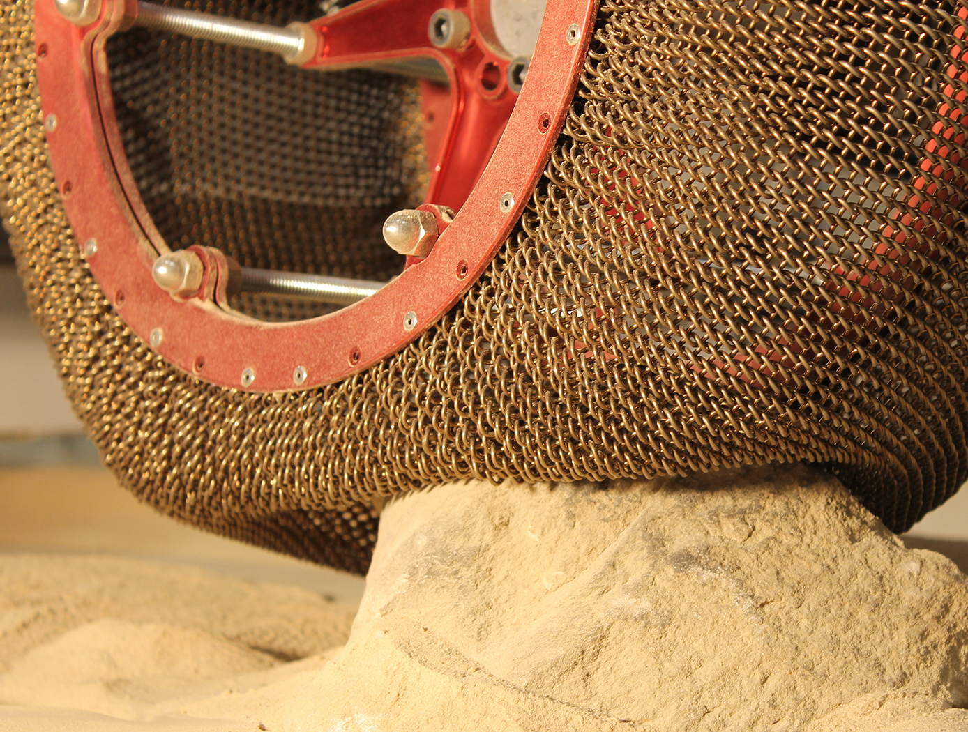
This NASA Glenn innovation comprises a non-pneumatic, compliant tire utilizing shape memory alloys (mainly NiTi and its derivatives) as load bearing components. These shape memory alloys are capable of undergoing significant reversible strain (up to 10%), enabling the tire to withstand an order of magnitude more deformation than other non-pneumatic tires before undergoing permanent deformation. Commonly used elastic-plastic materials (e.g. spring steels, composites, etc.) can only be subjected to strains on the order of ~ 0.3-0.5% before yielding. Hence, the use of a NiTi shape memory alloy produces a superelastic tire that is virtually impervious to plastic deformation. In addition, the utilization of shape memory alloys provides enhanced control over the effective stiffness as a function of the deformation, providing increased design versatility. For instance, the Glenn Superelastic Tire can be made to soften with increased deflection, reducing the amount of energy transferred to the vehicle during high deformation events. In addition, the use of shape memory alloys in the form of radial stiffeners, as opposed to springs, provides even more load carrying potential and improved design flexibility. This type of compliant tire would allow for increased travel speeds in off-road applications.

High-Temperature Single Crystal Preloader
For extremely high-temperature sealing applications, Glenn researchers have devised novel methods for fabricating single-crystal preloaders. NASA's high-temperature preloaders consist of investment cast or machined parts that are fabricated in various configurations from single crystal superalloys. Machined preloaders include a variety of spring configurations, compressed axially or radially, fabricated from single crystal slabs. Before machining, the slabs are carefully oriented in a special goniometer using x-diffraction techniques. This helps to maintain proper crystal orientation relative to the machined part and the applied loads. For more complex geometry components which cannot be easily and economically machined, an investment casting approach would be used. Complex preloader geometries include wire coil springs of various configurations. These single crystal preloaders would be designed with the appropriate stiffness for the intended thermal barrier/seal application and placed underneath, or integrated within, the seal/barrier. At extrememly high temperature, the preload device keeps the seal/barrier mated against the opposing surface as the gap between the two surfaces changes, maintaining contact between surfaces and preventing convective heat transfer.
Feedthrough for Severe Environments and Temperatures
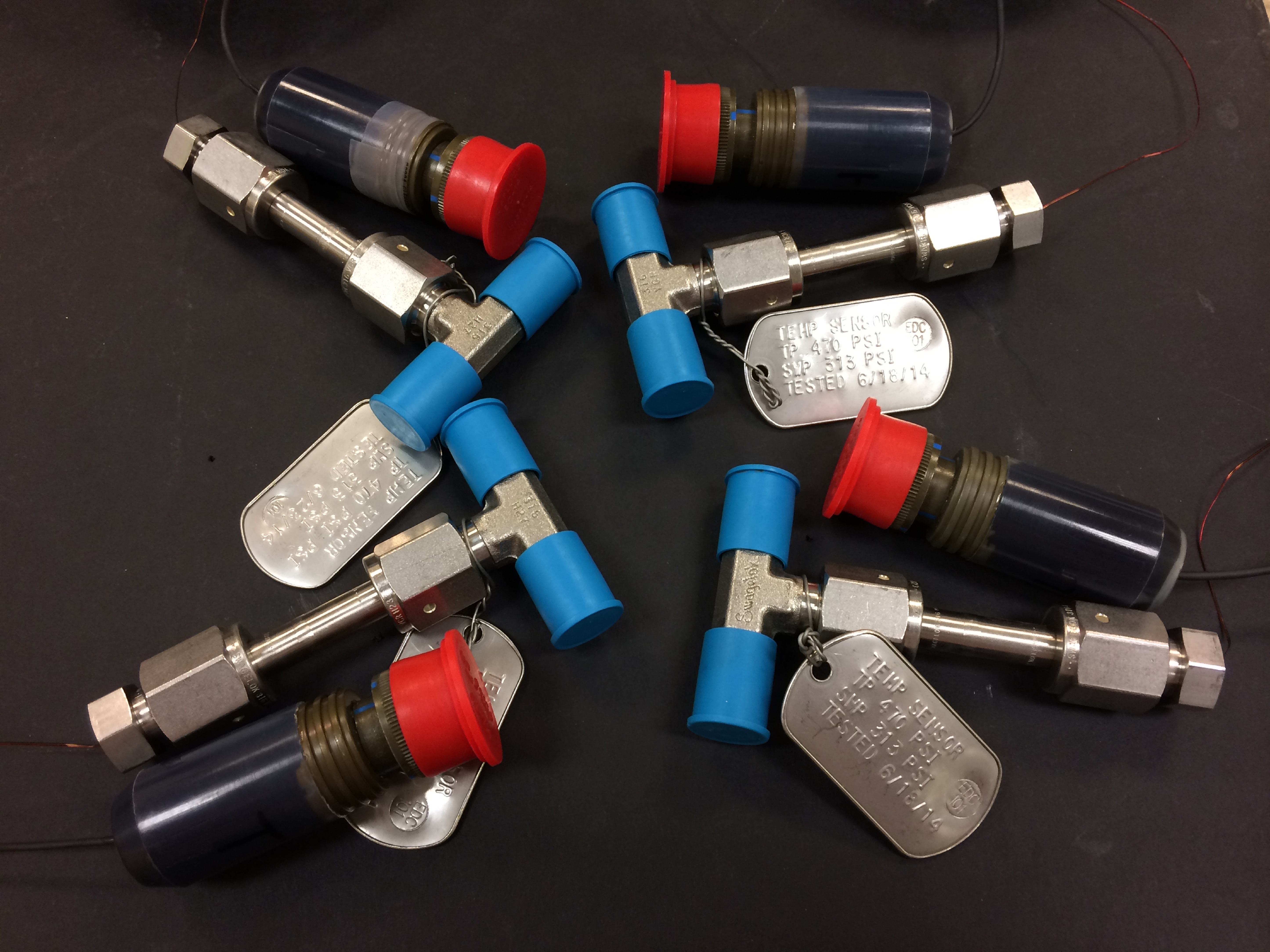
Space and ground launch support related hardware often operate under extreme pressure, temperature, and corrosive conditions. When dealing with this type of equipment, it is frequently necessary to run wiring, tubes, or fibers through a barrier separating one process from another with one or both operating in extreme environments. Feedthroughs used to route the wiring, tubes, or fibers through these barriers must meet stringent sealing and leak tightness requirements.
This affordable NASA feedthrough meets or exceeds all sealing and leak requirements utilizing easy-to-assemble commercial-off-the-shelf hardware with no special tooling. The feedthrough is a fully reconfigurable design; however, it can also be produced as a permanent device. Thermal cycling and helium mass spectrometer leak testing under extreme conditions of full cryogenic temperatures and high vacuum have proven the sealing capability of this feedthrough with or without potting (epoxy fill) on the ends. Packing material disks used in the construction of the device can be replaced as needed for rebuilding a given feedthrough for another job or a different set of feeds if potting is not used for the original feedthrough build. (Potting on one or both sides of the sleeve provides double or triple leak sealing protection). Variable Compression Ratio (VCR) connectors were adapted for the pressure seal on the feedthrough; however, any commercial connector can be similarly adapted. The design can easily be scaled up to larger (2" diameter) and even very large (12" or more) sizes.
Variable-Aperture Reciprocating Reed (VARR) Valve
The VARR valve has been designed to provide a variable-size aperture that proportionately changes in relation to gas flow demand. When the pressure delta between two chambers is low, the effective aperture cross-sectional area is small, while at high delta pressure the effective aperture cross-sectional area is large. This variable aperture prevents overly restricted gas flow. As shown in the drawing below, gas flow through the VARR valve is not one way. Gas flow can traverse through the device in a back-and-forth reversing flow manner or be used in a single flow direction manner. The contour shapes and spacing can be set to create a linear delta pressure vs. flow rate or other pressure functions not enabled by current standard orifices. Also, the device can be tuned to operate as a flow meter over an extremely large flow range as compared to fixed-orifice meters. As a meter, the device is capable of matching or exceeding the turbine meter ratio of 150:1 without possessing the many mechanical failure modes associated with turbine bearings, blades, and friction, etc.

Seal with Integrated Shroud to Protect from Exposure to Extreme Environments
Approximately 50 inches in diameter, Glenn's unique sealing system consists of multiple elements installed in a recessed rectangular sealing groove. The main sealing function is provided by an elastomer element (e.g., silicone) comprising one or more sealing wall(s) connected by a web. The wall(s) extend above the top of the sealing groove so they are compressed by the opposing mating surface during the sealing process. The retractable shroud element is installed between the wall(s), with its base resting atop the web of the sealing element. The shroud is typically composed of an elastomer material to allow for flexibility (which is essential to retraction), but it can also be made from thin metal or plastic materials. When the seal is no longer in use, a pair of V-shaped shroud "arms" extend upward from the base of the seal to cover the wall(s). A thin metal retainer is installed on top of the shroud, and fasteners pass through holes in the retainer, shroud, and sealing elements to secure the system to the base of the sealing groove. Metal washers are installed in these holes to provide a load path between the metal retainer and the surface of the sealing groove. The system can seal against either a flat metal surface or another seal of the same design. This sealing system has been designed to accommodate multiple sealing cycles and has exhibited extremely low leak rates, making it an attractive solution within a variety of industries from aerospace to agriculture.

Gear Bearings
These patented gear bearings provide superior speed reduction in a small package. They form rolling friction systems that function both as gears and bearings and are compatible with most gear types, including spur, helical, elliptical, and bevel gears. These self-synchronized components can be in the form of planets, sun, rings, racks, and segments thereof. The design reduces micro chatter and eliminates rotational wobble to create smooth and precise control. It offers tighter mesh, more even gear loading, and reduced friction and wear.
Gear bearings eliminate separate bearings, inner races, and carriers, as well as intermediate members between gears and bearings. Load paths go directly from one gear bearing component to another and then to ground. By incorporating helical gear teeth forms (including herringbone), gear bearings provide outstanding thrust bearing performance. They also provide unprecedented high- and low-speed reduction through the incorporation of phase tuning. Phase tuning allows differentiation in the number of teeth that must be engaged govbetween input and output rings in a planetary gearset, enabling successful reduction ratios of 2:1 to 2,000:1. They provide smooth and accurate control with rifle-true anti-backlash. This produces a planetary transmission with zero backlash. The gear bearing technology is based on two key concepts: the roller gear bearing and the phase-shifted gear bearing. All designs are capable of efficiently carrying large thrust loads.
Existing gear systems have drawbacks including weak structures, large size, and poor reliability, as well as high cost for some types (e.g., harmon-ic drives). Gear bearings solve these problems with simpler construction, fewer parts, and superior strength.
By selecting the appropriate manufacturing method and materials, gear bearings can be tailored to benefit any application, from toys to aircraft.
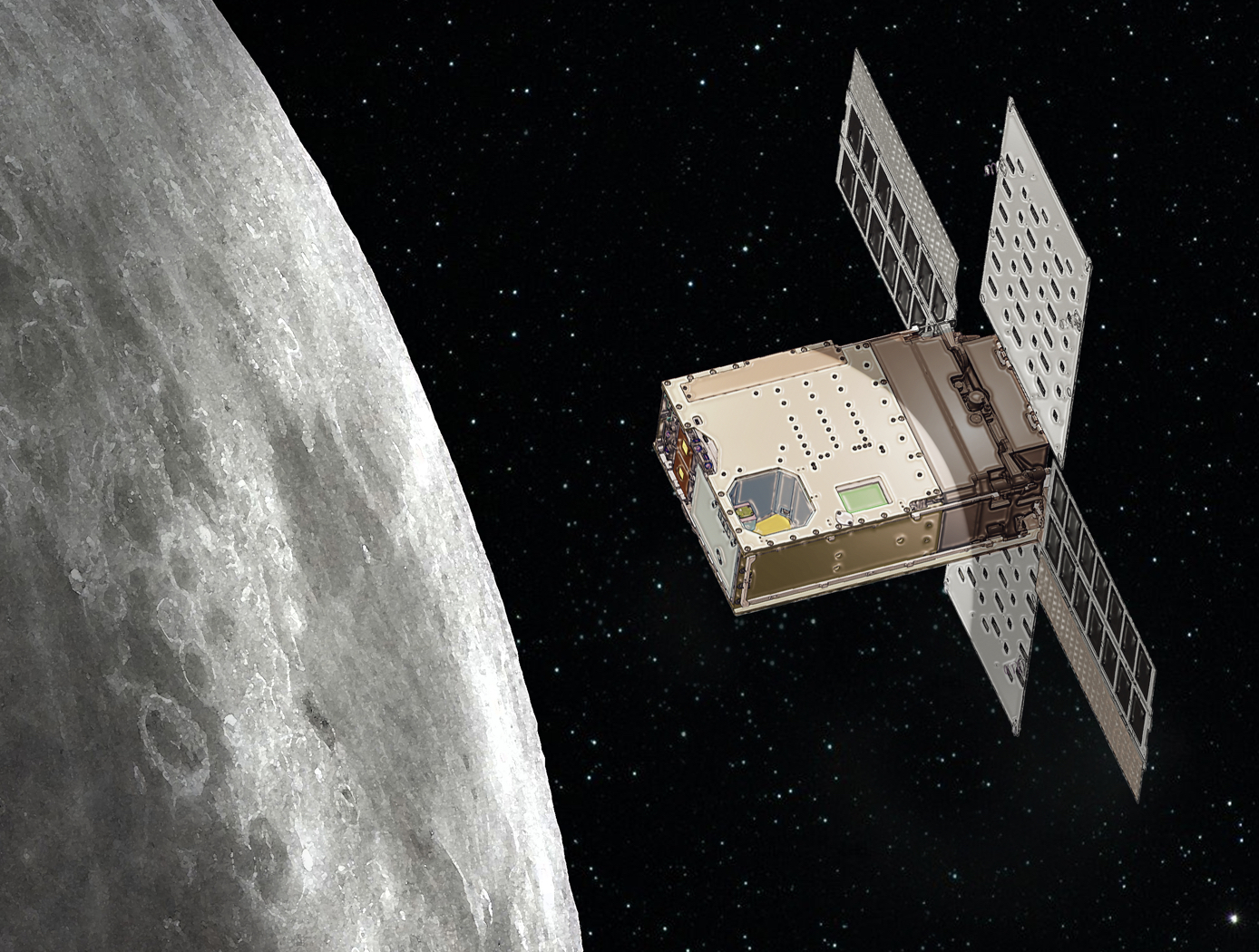
Miniature Separable Fill & Drain Valve
The Miniature Separable Fill & Drain Valve consists of two halves (ground and flight). The flight half is attached to the vehicle (i.e., CubeSat), and the ground half can be inserted into the vehicle in the same port as the flight half, connecting the two halves together. In normal state, the flight half seals the flow path. When the ground half is connected, the flow path is opened, allowing connected ground support equipment to supply fluid through the valve. The valve is manually operated.
There are redundant seals to eliminate leakage around the valve, including NASA's previously-patented Low-Cost, Long Lasting Valve Seal design (Patent No. 10,197,165; see MFS-TOPS-71 in the Links section of this flyer for more information) on the flight half. This eliminates the need for a swaged assembly process and the additional hardware and equipment that are typically required in conventional, elastomeric valve seat installations. The design also includes a cap for the flight half to ensure there is no leakage in flight configuration.
The Miniature Separable Fill & Drain Valve has been prototyped and provides valuable benefits for CubeSat applications. The valve could also have applications in the industrial processing industry where low flow devices are commonly used. The design is also scalable to larger applications where the removal of the actuation device would be desired.
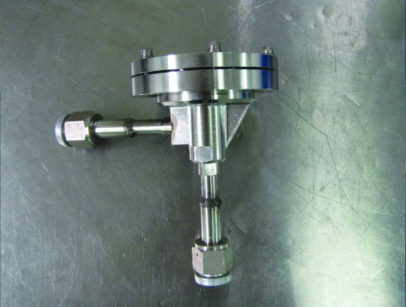
Pilot Assisted Check Valve for Low Pressure Applications
Check valves are traditionally designed as a simple poppet/spring system where the spring is designed to equal the force created from the sealing area of the valve seat multiplied by the cracking pressure. Since the valve seat diameter in these types of valves are relatively small, less than 0.5 inches diameter, a low cracking pressure required for back pressure relief devices results in a low spring preload. When sealing in the reverse direction, the typical 20 psid storage pressure of the cryogenic fluid is not enough pressure force to provide adequate sealing stress. To better control the cracking pressure and sealing force, a bellows mechanism was added to a poppet check valve (see Figure 2). The bellows serves as a reference pressure gauge; once the targeted pressure differential is reached, the bellows compresses and snaps the valve open. Prior to reaching the desired crack pressure differential, the bellows diaphragm is fully expanded, providing sufficient seal forces to prevent valve flow (including reverse flow) and undesired internal leakage. Room temperature testing of cracking pressure, full flow pressure, and flow capacity all showed improvements. The overall results of the test proved to be 10-20 times greater than conventional check valves with no internal leakage at three different pressure differentials.
View more patents


