Search
Instrumentation

Dual-Polarized, Wideband, Lightweight P-band Antenna Element and Array
The P-band antenna array is built from rows and columns of antenna elements for the purpose of allowing beam steering up to the maximum desirable angle without incurring grating lobes in the radiation patterns. For flexible mission planning, a large array can be built from several of the small, panel-like elements. The elements are deployable from a folded or stacked stowed configuration during launch, arranged side by side during operation. Each antenna element is itself a fully functional small antenna array. The number of panels can be chosen as dictated by the mission objectives and budget.
Three geometries were designed and tested. Geometry 1 features non-planar metal structures with minimal dielectric support, where the back cavity is closed. Geometry 2 features non-planar metal structures with minimal composite sheet dielectric support, but with an open cavity. Both geometries avoid large flat sheets, which are vulnerable to bending, thereby increasing the mechanical stiffness of the structure while using only thin sheet metal and maintaining an exceptionally low mass-to-size ratio. Geometry 3 features planar metal structures, with sandwich composite dielectric support and an open cavity. While it does not benefit from the mechanical stiffness utilized in non-planar designs, the planar sandwich structure increase robustness and reduces the cost of fabrication. All element geometries have wideband capabilities and are dual polarized.
Although designed for space and planetary exploration, the P-band antenna is also valuable for various terrestrial use cases. The P-band antenna array is at technology readiness level (TRL) 5 (component and/or breadboard validation in relevant environment) and is available for patent licensing.
communications
Fine-pointing Optical Communication System Using Laser Arrays
A new method is described for optical data transmissions from satellites using laser arrays for fine pointing of laser beams that use body pointing. It combines a small lens system and a VCSEL/Photodetector Array in a novel way to provide a fine pointing capability for laser beams that are pointed by body pointing of a CubeSat. As Fig. 1 shows, an incoming laser beam (green or blue, with rightward arrows), transmitted from a ground terminal, enters the lens system, which directs it to an element of the pixel array (gray rectangle). Each element, or pixel, consists of a VCSEL component/photodetector pair. The photodetector detects the incoming beam, and the VCSEL component returns a modulated beam to the lens system (green or blue, with leftward arrows), which sends it to the ground terminal. As the incoming beam changes direction, e.g., from the blue to the green incoming direction, this change is detected by the adjacent photodetector, and the laser paired with that photodetector is turned on to keep the outgoing laser beam on target. The laser beams overlap so that the returning beam continues to point at the ground terminal. The VCSEL component may consist of a single VCSEL or a cluster of VCSELs. Figure 2 shows the propagation of two overlapping laser beams. The system can very accurately point finely focused diffraction-limited laser beams. Also, simultaneous optical multiple access (OMA) is possible from different transceivers within the area covered by the laser array. For this electro-optical system, reaction times to pointing changes and vibrations are on the nanosecond time scale, much faster than mechanical fine pointing systems.
Instrumentation

Sensitive, Compact 1x8 Array 530-600 GHz Receiver
This NASA invention is a highly compact and sensitive 530-600 GHz, 1x8 receiver array employing a multi-pixel approach to enhance simultaneous detection capabilities. The receiver has a conversion loss of <11dB, noise temperature of less than 2000 K at 540 GHz, and a wide IF bandwidth of ~70 GHz. The system reduces size, weight, and power consumption (SWaP) by 3-4x and increases sensitivity by factor of 2x or more relative to current state-of-the-art cascaded systems.
The invention includes a power splitter circuit with an attenuation card, a mixer circuit coupled to an output of the power splitter circuit, and an antenna assembly coupled to an output of the mixer circuit. The splitter is a four-port waveguide designed with high position tolerance, and the waveguide attenuator provides a better than 20dB attenuator and balances the power split. A compact and high-efficiency Tripler circuit is integrated into the array system, that multiplies input frequency by a factor of 3. The system includes a sensitive, broadband sub-harmonic mixer circuit for 530-600 GHz frequency band operation (enabling the simultaneous detection of more than fourteen molecular species in this range e.g., water, deuterium oxide, oxygen, etc.) and integrated diagonal horn antennas to provide 24 dB gain with 9mm antenna spacing. Note that while originally designed for the 530-600 GHz band for remote sensing purposes, the design topology of the receiver can be easily scaled to support frequencies ranging from 1 GHz to > 1 THz and the center frequency can be tuned by adjusting design parameters.
While NASA originally developed this receiver to enable miniaturized, low power consumption, high sensitivity heterodyne-based submillimeter wave spectrometers for small satellite-based planetary atmospheric sensing, potential applications of the novel receiver are broad. The multi-pixel, wideband receiver can be used in spectrometer and radar systems for applications including astronomy, plasma fusion, military, and emerging communication technologies such as 5G and 6G. The invention is available for patent licensing.
Robotics Automation and Control

Robotic Assembly of Photovoltaic Arrays
NASA researchers have developed the PAPA technology to increase the efficiency of the thin-film solar array assembly process, significantly decreasing assembly time and labor costs associated with manufacturing large scale solar arrays. Traditional solar cell assembly is a labor intensive, multi-step, time-consuming process. This manual assembly will not be possible in a space environment. To enable solar array assembly in space, PAPA leverages robotic automation to distill the traditional assembly method into four fully automated steps: applying adhesive to block substrate, placing the solar cells using a vacuum tool attached to a universal robotic arm, printing the interconnects and buses to connect the cells, and applying a protective cover.
The PAPA technology is compatible with a variety of thin-film solar cells, including 3D printed cells (essential for future in-space manufacturing of arrays) and terrestrial manufacturing methods. As solar cell technologies mature, PAPA will be able to incorporate advancements into the paneling process. NASA researchers have begun to employ PAPA solar array fabrication and estimate savings of $300-$400/watt. For extraterrestrial assembly of solar panels the size of a football field or larger, PAPA could result in savings of approximately $500 million; a substantial cost savings driven by standardization and efficiency in the solar array assembly process. By demonstrating increases in assembly efficiency, time and cost savings, and passing multiple environmental exposure tests, the PAPA lab protype has completed the final phases of technology development and is ready for scale-up and commercialization.
Health Medicine and Biotechnology
Electrochemical Sensors Based on Enzyme-Linked Immunosorbent Assay
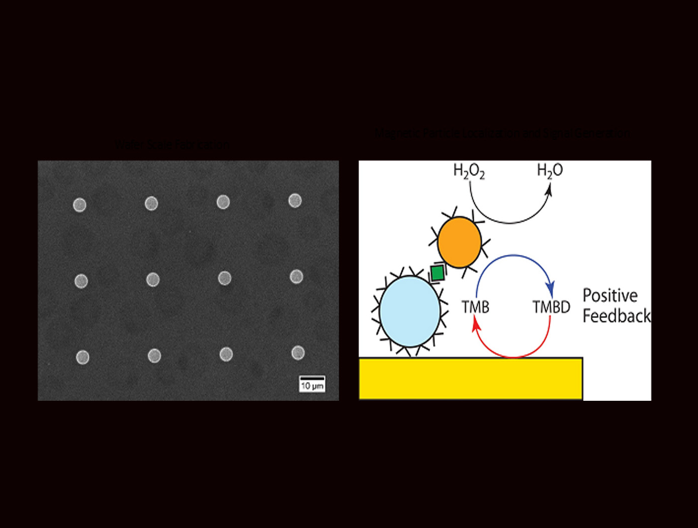
NASA’s electrochemical Enzyme-Linked Immunosorbent Assay (ELISA) microelectrode array biosensor advantageously incorporates a microbead detection construct, coupled with a magnetic immobilization construct, which substantially increases the signal sensitivity of a sensor. The magnetic immobilization construct draws the microbead detection construct to an electrode detection surface, enhancing signal sensitivity. By concentrating the signaling molecules close to the electrode detection surface, electrochemical redox cycling is achieved by reducing the distance between the two, allowing for regeneration of reporter molecules.
Whereas a traditional ELISA testing exhibits five to ten signaling molecules per probe molecule binding event, the present electrochemical ELISA-based biosensor testing exhibits up to 4,857 signaling molecules per probe molecule binding event. The model bead construct exhibits a more than 6.75-fold in increased measured signal, and more than 35.7-fold improvement in signal sensitivity. When compared to traditional optical ELISA, the present invention improves the limit of detection by up to a factor of 60.5.
NASA’s electromagnetic ELISA-based biosensor can be used for the detection of SARS-CoV-2 virus to enhance Covid-19 testing during the early phases of infection. The technology may also be modified to detect other biomarkers.
Communications
Conformal, Lightweight, Aerogel-Based Antenna
This CLAS-ACT is a lightweight, active phased array conformal antenna comprised of a thin multilayer microwave printed circuit board built on a flexible aerogel substrate using new methods of bonding. The aerogel substrate enables the antenna to be fitted onto curved surface. NASA's prototype operates at 11-15 GHz (Ku-band), but the design could be scaled to operate in the Ka-band (26 to 40 GHz).
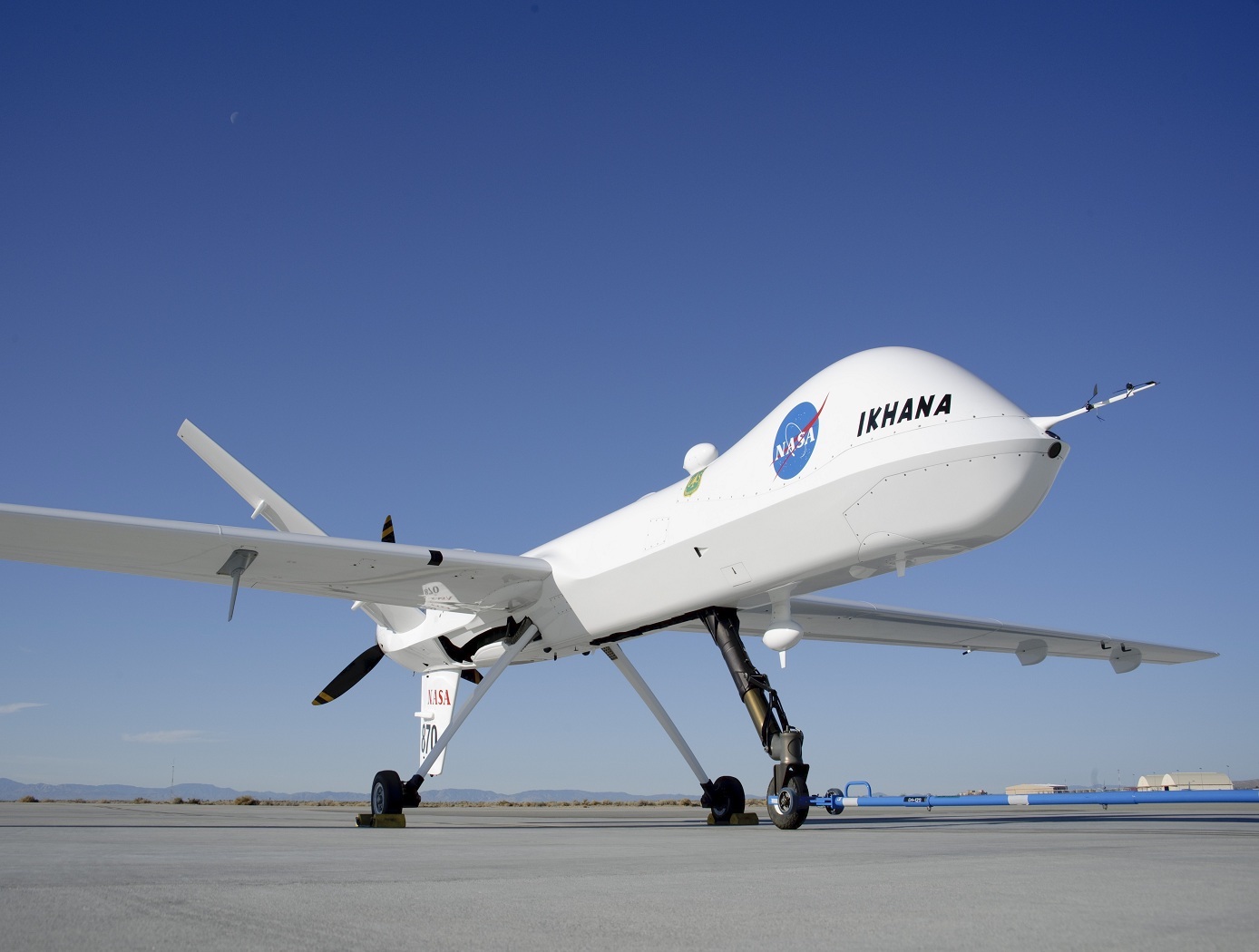
The antenna element design incorporates a dual stacked patch for wide bandwidth to operate on both the uplink and downlink frequencies with a common aperture. These elements are supported by a flexible variant of aerogel that allows the material to be thick in comparison to the wavelength of the signal with little to no additional weight. The conformal antenna offers advantages of better aerodynamics for the airframe, and potentially offers more physical area to either broadcast further distances or to broadcast at a higher data rate. The intended application for this antenna is for UAVs that need more than line of sight communications for command and control but cannot accommodate a large satellite dish. Examples may be UAVs intended for coastal monitoring, power line monitoring, emergency response, and border security where remote flying over large areas may be expected. Smaller UAVs may benefit greatly from the conformal antenna. Another possible application is a UAV mobile platform for Ku-band satellite communication.
With the expectation that 5G will utilize microwave frequencies this technology may be of interest to other markets outside of satellite communications. For example, the automotive industry could benefit from a light weight conformal phased array for embedded radar. Also, the CLAS-ACT could be used for vehicle communications or even vehicle to vehicle communications.
communications
Lightweight, Self-Deployable Helical Antenna
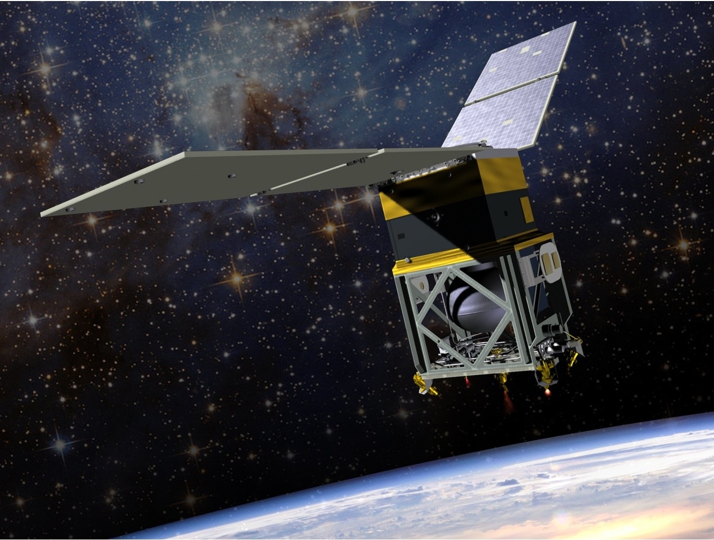
NASA's newly developed antenna is lightweight (at or below 2 grams), low volume (at or below 1.2 cm3), and low stowage thickness (approx. 0.7 mm), all while delivering high performance (at or above 10 dBi gain). The antenna includes a novel design-material combination in a helical coil conformation. The design allows the antenna to compress for stowage (e.g., satellite launch), then self-deploy at the desired time in orbit.
NASA's lightweight, self-deployable helical antenna can be integrated into a thin-film solar array (or other large deployable structures). Integrating antenna elements into deployable structures such as power generation arrays allows spacecraft designers to maximize the inherently limited resources (e.g., mass, volume, surface area) available in a small spacecraft. When used as a standalone (i.e., single antenna) setup, the the invention offers moderate advantages in terms of stowage thickness, volume, and mass. However, in applications that require antenna arrays, these advantages become multiplicative, resulting in the system offering the same or higher data rate performance while possessing a significantly reduced form factor.
Prototypes of NASA's self-deployable, helical antenna have been fabricated in S-band, X-band, and Ka-band, all of which exhibited high performance. The antenna may find application in SmallSat communications (in deep space and LEO), as well as cases where low mass and stowage volume are valued and high antenna gain is required.
Information Technology and Software
Unique Datapath Architecture Yields Real-Time Computing
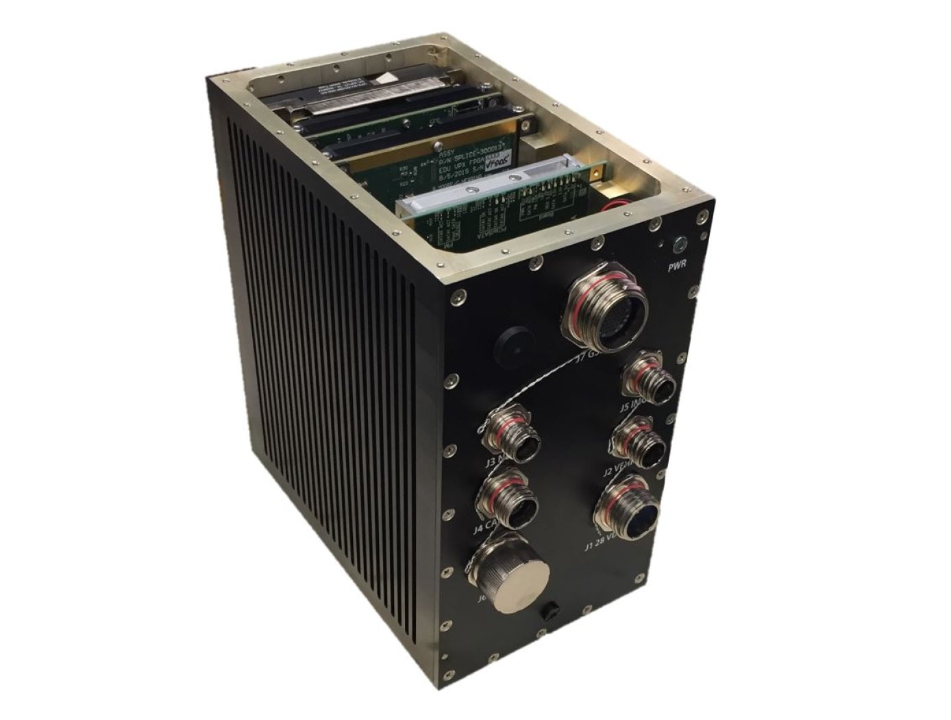
The DLC platform is composed of three key components: a NASA-designed field programmable gate array (FPGA) board, a NASA-designed multiprocessor on-a-chip (MPSoC) board, and a proprietary datapath that links the boards to available inputs and outputs to enable high-bandwidth data collection and processing.
The inertial measurement unit (IMU), camera, Navigation Doppler Lidar (NDL), and Hazard Detection Lidar (HDL) navigation sensors (depicted in the diagram below) are connected to the DLC’s FPGA board. The datapath on this board consists of high-speed serial interfaces for each sensor, which accept the sensor data as input and converts the output to an AXI stream format. The sensor streams are multiplexed into an AXI stream which is then formatted for input to a XAUI high speed serial interface. This interface sends the data to the MPSoC Board, where it is converted back from the XAUI format to a combined AXI stream, and demultiplexed back into individual sensor AXI streams. These AXI streams are then inputted into respective DMA interfaces that provide an interface to the DDRAM on the MPSoC board. This architecture enables real-time high-bandwidth data collection and processing by preserving the MPSoC’s full ability.
This sensor datapath architecture may have other potential applications in aerospace and defense, transportation (e.g., autonomous driving), medical, research, and automation/control markets where it could serve as a key component in a high-performance computing platform and/or critical embedded system for integrating, processing, and analyzing large volumes of data in real-time.
Sensors

Advanced Thermal Inspection with Pulsed Light Emitting Diodes (PLED) Technology
NASA’s PLED thermal inspection system consists of an array of high- powered LED chips configured to deliver controlled pulses of visible light. The system includes 8 LED chip arrays, mounted on an aluminum heat sink and housed in a hood configuration. The inspection hood is specially designed with filters to prevent internal reflections. The LEDs are powered by regulated power supplies and controlled via a computer interface that synchronizes heat pulses with an infrared camera. An acrylic filter is placed over the LEDs to block residual infrared radiation, ensuring that only visible light reaches the target surface. The system’s infrared camera, operating in the mid-wave infrared (MWIR) range does not detect the visible light and captures the transient thermal response of the material, allowing for precise defect detection. By eliminating the need for high-intensity broadband infrared sources, the PLED system provides a cleaner and more accurate thermal response, particularly for unpainted metals and additively manufactured (AM) components.
Performance validation of the PLED system has demonstrated significant advantages over traditional flash thermography. In tests on aluminum samples with material loss and AM Ti-6Al-4V metal specimens, the PLED system successfully detected defects with superior contrast and no heat source reflections. Principal Component Analysis (PCA) applied to PLED inspection data revealed clearer defect indications compared to flash-based methods, which introduced unwanted artifacts due to transient reflections. Additionally, the PLED system enabled quantitative thermal diffusivity measurements, offering a new approach to single-sided material characterization.
NASA's PLED thermal inspection technology is available for patent licensing. Potential applications include corrosion detection in aerospace components, quality control of AM metal parts, structural health monitoring of industrial materials, and more.

