Search
information technology and software
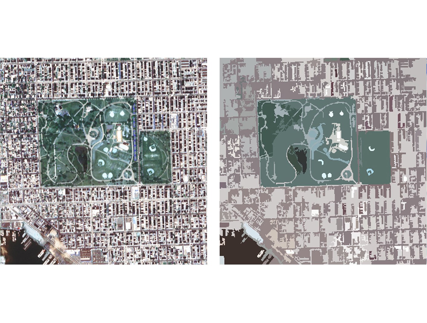
Hierarchical Image Segmentation (HSEG)
Currently, HSEG software is being used by Bartron Medical Imaging as a diagnostic tool to enhance medical imagery. Bartron Medical Imaging licensed the HSEG Technology from NASA Goddard adding color enhancement and developing MED-SEG, an FDA approved tool to help specialists interpret medical images.
HSEG is available for licensing outside of the medical field (specifically for soft-tissue analysis).
sensors

Method and Device for Biometric Verification and Identification
The advantage of using cardiac biometrics over existing methods is that heart signatures are more difficult to forge compared to other biometric devices. Iris scanners can be fooled by contact lenses and sunglasses, and a segment of the population does not have readable fingerprints due to age or working conditions. Previous electrocardiographic signals employed a single template and compared that template with new test templates by means of cross-correlation or linear-discriminant analysis.The benefit of this technology over competing cardiac biometric methods is that it is more reliable with a significant reduction in error rates. The benefit of this technology is that it creates a probabilistic model of the electrocardiographic features of a person instead of a single signal template of the average heartbeat. The probabilistic model described as Gaussian mixture model allows various modes of the feature distribution, in contrast to a template model that only characterizes a mean waveform. Another advantage is that the model uses both physiological and anatomical characterization of the heart, unlike other methods that mainly use only physiological characterization of the heart. By combining features from different leads, the heart of the person is better characterized in terms of anatomical orientation because each lead represents a different projection of the electrical vector of the heart. Thus, employing multiple electrocardiographic leads provides a better performance in subject verification or identification.
optics

Video Acuity Measurement System
The Video Acuity metric is designed to provide a unique and meaningful measurement of the quality of a video system. The automated system for measuring video acuity is based on a model of human letter recognition. The Video Acuity measurement system is comprised of a camera and associated optics and sensor, processing elements including digital compression, transmission over an electronic network, and an electronic display for viewing of the display by a human viewer. The quality of a video system impacts the ability of the human viewer to perform public safety tasks, such as reading of automobile license plates, recognition of faces, and recognition of handheld weapons. The Video Acuity metric can accurately measure the effects of sampling, blur, noise, quantization, compression, geometric distortion, and other effects. This is because it does not rely on any particular theoretical model of imaging, but simply measures the performance in a task that incorporates essential aspects of human use of video, notably recognition of patterns and objects. Because the metric is structurally identical to human visual acuity, the numbers that it yields have immediate and concrete meaning. Furthermore, they can be related to the human visual acuity needed to do the task. The Video Acuity measurement system uses different sets of optotypes and uses automated letter recognition to simulate the human observer.
information technology and software

Otoacoustic Protection In Biologically-Inspired Systems
This innovation is an autonomic method capable of transmitting a neutralizing data signal to counteract a potentially harmful signal. This otoacoustic component of an autonomic unit can render a potentially harmful incoming signal inert. For selfmanaging systems, the technology can offer a selfdefense capability that brings new levels of automation and dependability to systems.
information technology and software

Inductive Monitoring System
The Inductive Monitoring System (IMS) software provides a method of building an efficient system health monitoring software module by examining data covering the range of nominal system behavior in advance and using parameters derived from that data for the monitoring task. This software module also has the capability to adapt to the specific system being monitored by augmenting its monitoring database with initially suspect system parameter sets encountered during monitoring operations, which are later verified as nominal. While the system is offline, IMS learns nominal system behavior from archived system data sets collected from the monitored system or from accurate simulations of the system. This training phase automatically builds a model of nominal operations, and stores it in a knowledge base. The basic data structure of the IMS software algorithm is a vector of parameter values. Each vector is an ordered list of parameters collected from the monitored system by a data acquisition process. IMS then processes select data sets by formatting the data into a predefined vector format and building a knowledge base containing clusters of related value ranges for the vector parameters. In real time, IMS then monitors and displays information on the degree of deviation from nominal performance. The values collected from the monitored system for a given vector are compared to the clusters in the knowledge base. If all the values fall into or near the parameter ranges defined by one of these clusters, it is assumed to be nominal data since it matches previously observed nominal behavior. The IMS knowledge base can also be used for offline analysis of archived data.
sensors

Detection Of Presence Of Chemical Precursors
These needs are met by this invention, which provide easy stem and associated method for detecting one or more chemical precursors (components) of a multi-component explosive compound. Different carbon nanotubes (CNTs) are loaded (by doping, impregnation, coating, or other functionalization process) for detecting of different chemical substances that are the chemical precursors, respectively, if these precursors are present in a gas to which the CNTs are exposed. After exposure to the gas, a measured electrical parameter (e.g. voltage or current that correlate to impedance, conductivity, capacitance, inductance, etc.) changes with time and concentration in a predictable manner if a selected chemical precursor is present, and will approach an asymptotic value promptly after exposure to the precursor.
The measured voltage or current are compared with one or more sequence soft heir reference values for one or more known target precursor molecules, and a most probable concentration value is estimated for each one, two, or more target molecules. An error value is computed, based on differences of voltage or current for the measured and reference values, using the most probable concentration values. Where the error value is less than a threshold, the system concludes that the target molecule is likely. Presence of one, two, or more target molecules in the gas can be sensed from a single set of measurements.
sensors
Biomarker Sensor Arrays for Microfluidics Applications
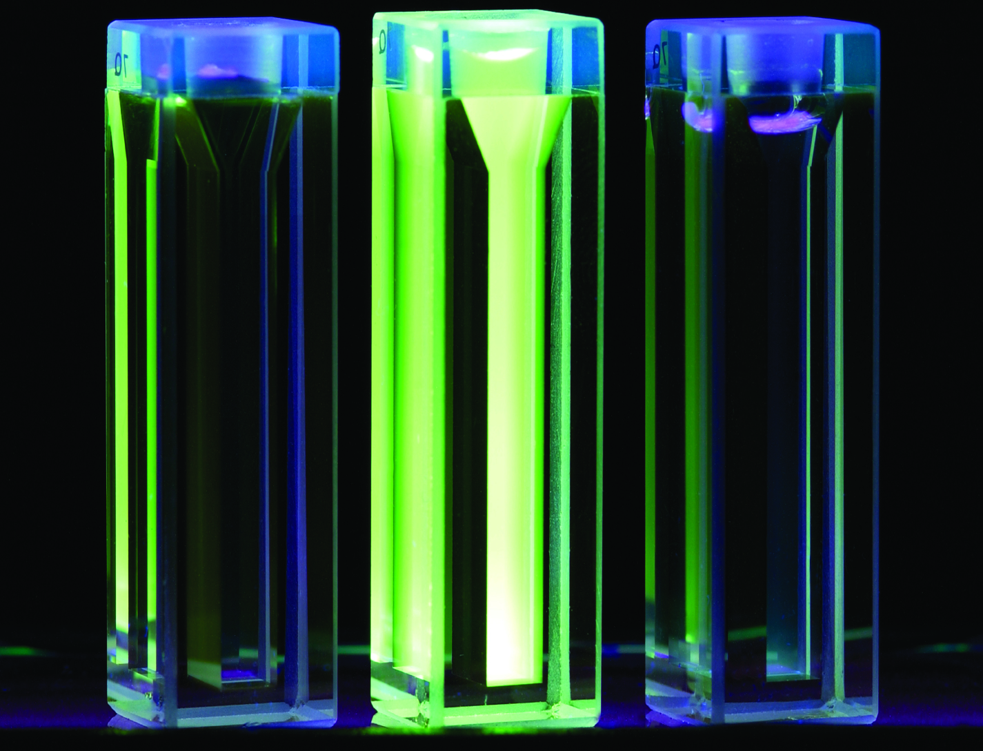
This invention provides a method and system for fabricating a biomarker sensor array by dispensing one or more entities using a precisely positioned, electrically biased nanoprobe immersed in a buffered fluid over a transparent substrate. Fine patterning of the substrate can be achieved by positioning and selectively biasing the probe in a particular region, changing the pH in a sharp, localized volume of fluid less than 100 nm in diameter, resulting in a selective processing of that region. One example of the implementation of this technique is related to Dip-Pen Nanolithography (DPN), where an Atomic Force Microscope probe can be used as a pen to write protein and DNA Aptamer inks on a transparent substrate functionalized with silane-based self-assembled monolayers. But it would be recognized that the invention has a much broader range of applicability. For example, the invention can be applied to formation of patterns using biological materials, chemical materials, metals, polymers, semiconductors, small molecules, organic and inorganic thins films, or any combination of these.
manufacturing
Fiber-Metal Laminate Manufacturing Technique
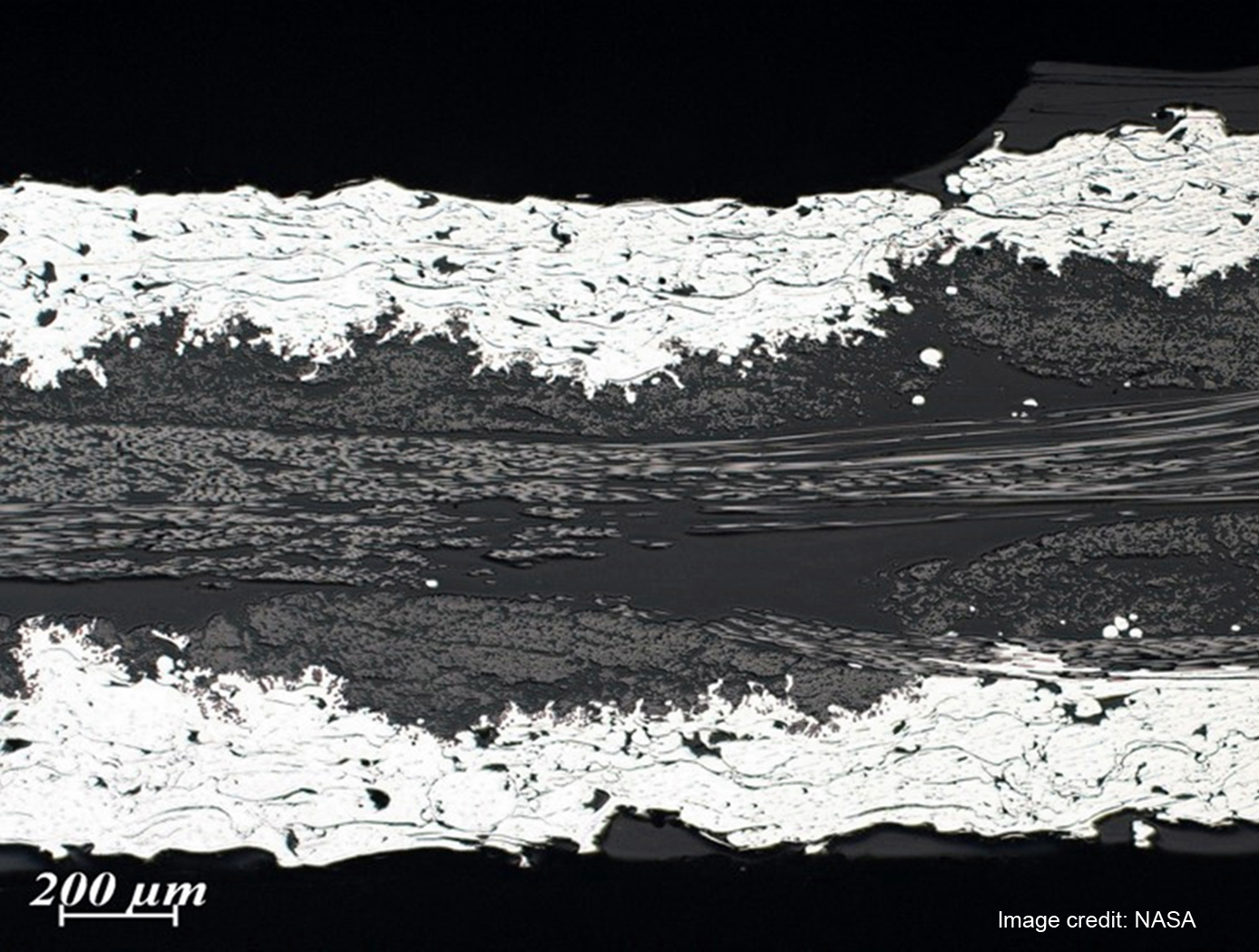
Fiber-Metal Laminates (FMLs) are composite materials that consist of conventional fiber reinforced plastics with the addition of a metal component, typically a foil or mesh layer(s). The metal component offers the advantage of incorporating metal-like properties to the composite construction. While a range of potential advantages and applications have been discussed for FMLs, the primary application to date has been for aircraft structures, with one potential advantage being the lightning strike protection (LSP) offered by the improved electrical conductivity. As aircraft construction has moved to composite structures, there has been an increasing need for such conductive composites. Similarly, with increasing use of composites for other large structures, e.g. wind turbines, there are an increasing number of potential applications for lightning strike protection materials. Other advantages of FML are improved impact and fire resistance.
This innovation provides a method for making FML materials that incorporate nanotube reinforcement. The method involves the use of RF plasma spray to directly form and deposit nanotube materials onto fibers/fabrics, which can then be manufactured into composite structures by infiltrating the fiber with resin, and consolidating the structure via autoclave processing or via the use Vacuum Assisted Resin Transfer Molding (VARTM) composite manufacturing methods. Nanotubes incorporated into the structure in this manner can be of several types, for example boron nitride or carbon nanotubes. The objective of this innovation is to incorporate the nanotube materials in the FML in order to improve the mechanical properties.
Sensors
Electric Field Imaging System
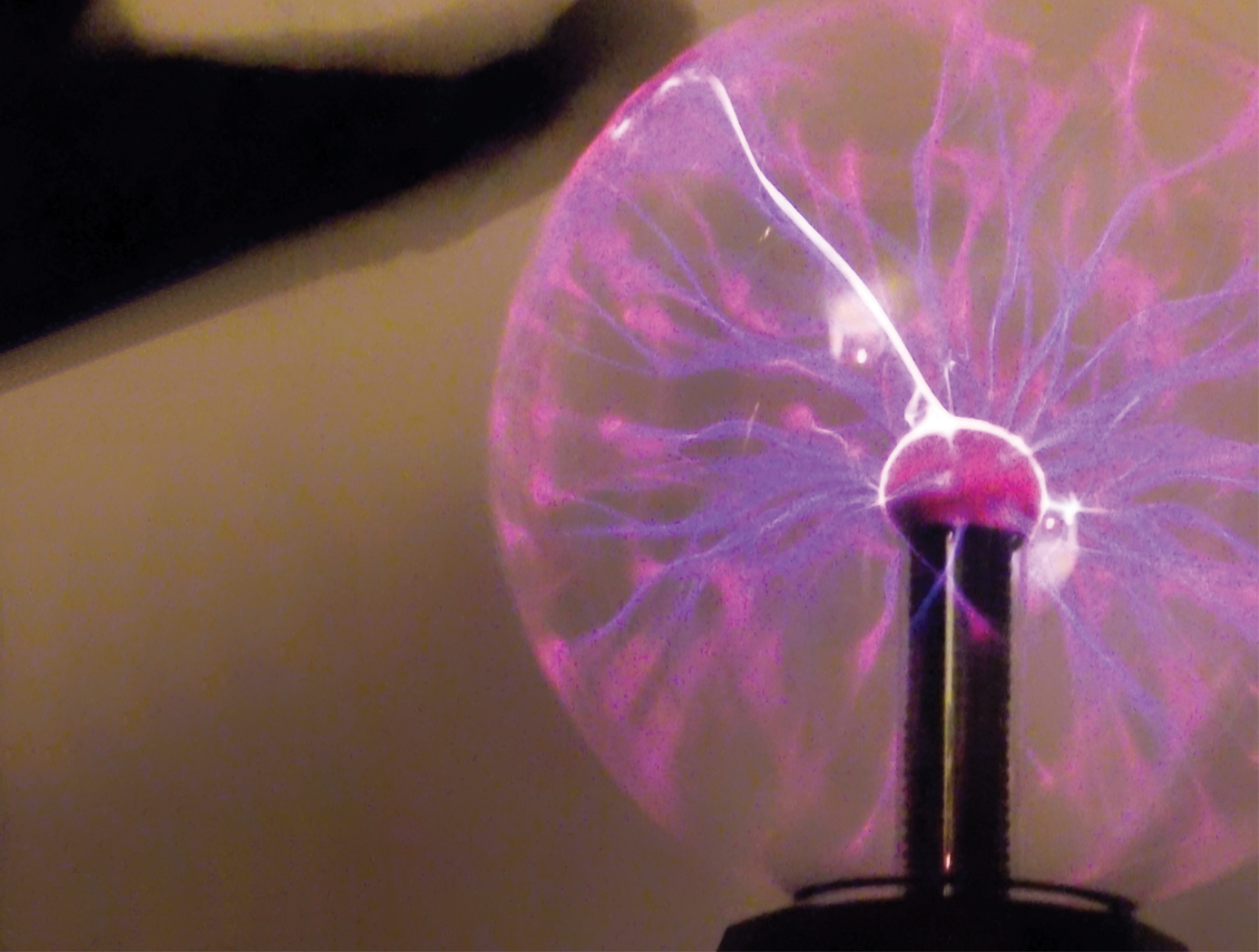
The EFI imaging platform consists of a sensor array, processing equipment, and an output device. By registering voltage differences at multiple points within the sensor array, the EFI system can calculate the electrical potential at points removed from the sensor. Using techniques similar to computed tomography, the electrical potential data can be assembled into a three-dimension map of the magnitude and direction of electric fields. Since objects interact with electric fields differently based on their shape and dielectric properties, this electric field data can then be used to understand shape,
internal structure, and dielectric properties (e.g., impedance, resistance) of objects in three dimensions.
The EFI sensor can be used on its own to see electric fields or image electric fieldemitting objects near the sensor (e.g., to evaluate leakage from poorly shielded wires or casings). For evaluation of objects that do not produce an electric field, NASA has developed generator that emits a low-current, human-safe electrostatic field for snapshot evaluation of objects. Additionally, an alternative EFI system optimized to evaluate electric fields at significant distances (greater than 1 mile) is being developed for weather-related applications.
sensors
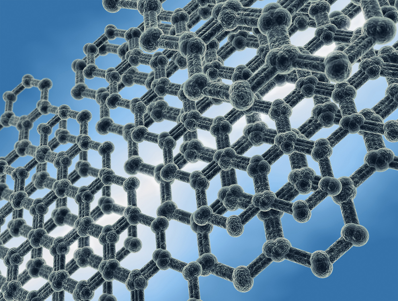
Electrical Response Using Nanotubes on a Fibrous Substrate
A resistor-type sensor was fabricated which has a network of cross-linked SWCNTs with purity over 99%. An ordinary cellulose paper used for filtration was employed as the substrate. The filter paper exhibits medium porosity with a flow rate of 60 mL/min and particle retention of 5-10m. The roughness and porosity of the papers are attractive because they increase the contact area with the ambient air and promote the adhesion to carbon nanotubes. The SWCNTs were functionalized with carboxylic acid (COOH) to render them hydrophilic, thus increasing the adhesion with the substrate. The functionalized SWCNTs were dispersed in dimethylformamide solution. The film composed of networks of cross-linked CNTs was formed using drop-cast coating followed by evaporation of the solvent. Adhesive copper foil tape was used for contact electrodes. Our sensors outperformed the oxide nanowire-based humidity sensors in terms of sensitivity and response/recovery times.


