SMART Solar Sail
propulsion
SMART Solar Sail (GSC-TOPS-16)
A super miniaturized autonomous reconfigurable technology solar sail
Overview
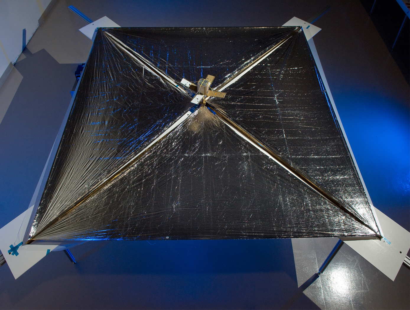
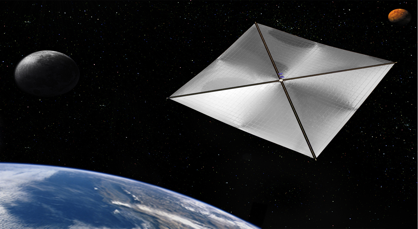
NASA GSFCs SMART (Super Miniaturized Autonomous Reconfigurable Technology) Solar Sail is a deployable, fully autonomous, solar sail for use in a very fine station keeping of a spacecraft. The solar sail would be highly deformable from an initially highly compressed configuration, yet also capable of enabling very fine maneuvering of the spacecraft by means of small sail-surface deformations. The SMART Solar Sail would be connected to the main body of the spacecraft by a SMART multi-tether structure, which would include microelectromechanical system (MEMS) actuators like those of the frame plus tethers in the form of longer versions of the struts in the frame.
The Technology
The SMART solar sail includes a reflective film stretched among nodes of a SMART space frame made partly of nanotubule struts. A microelectromechanical system (MEMS) at each vertex of the frame spools and unspools nanotubule struts between itself and neighboring nodes to vary the shape of the frame. The MEMSs is linked, either wirelessly or by thin wires within the struts, to an evolvable neural software system (ENSS) that controls the MEMSs to reconfigure the sail as needed. The solar sail is highly deformable from an initially highly compressed configuration, yet also capable of enabling very fine maneuvering of the spacecraft by means of small sail-surface deformations. The SMART Solar Sail is connected to the main body of the spacecraft by a SMART multi-tether structure, which includes MEMS actuators like those of the frame plus tethers in the form of longer versions of the struts in the frame.


Benefits
- Autonomous: The SMART Solar Sail is designed to be self-sufficient
- Highly deformable from from an initially highly compressed configuration
- Maneuverability: Capable of very fine maneuvering by small surface deformation
Applications
- NASA or private space missions involving the development of Solar Sails
|
Tags:
|
Similar Results

Low Creep, Low Relaxation Fiber-Reinforced Polymer Composites
NASA used three strategies to develop a family of modified epoxy resins for use in an improved composite layup configuration. By tailoring molecular structures, incorporating secondary additives, and adjusting composite architecture, NASA has produced fiber-reinforced polymer composites that suppress viscoelastic creep and relaxation. Specifically the three strategies were:
(1) Controlling the cross-linking density using reactive functional groups and selecting appropriate monomers with stoichiometry adjustments. A higher stoichiometric ratio is responsible for reduced relaxation compared to a lower ratio (resulting in 26% relaxation after 1 year vs. 49%).
(2) Increase the steric hindrance by reducing free volume and enhancing intermolecular interaction. This involved the preparation of two different reactive low molecular weight oligomers The best epoxy resin created was from the VCD/HAA additives with 15-17% relaxation; DEGBA/HAA had 22-25% relaxation.
(3) Optimizing different carbon fiber layup configurations for woven structures made into a highly stiff boom, highly flexible boom, a small size boom, and a large size boom application. The best configuration was that of a highly stiff boom with 4-5% relaxation. Other carbon fiber layup configurations had 16-30% relaxation.
As shown in the figure below, NASA tested the relaxed composite using an accelerated test with variable temperatures.

Multi-Link Spherical Joint
The Multi-Link Spherical Joint developed at NASA Johnson Space Center provides a substantial improvement over typical joints in which only two linearly actuated links move independently from one another. It was determined that the rotation point of a trussed link needed to be collocated at a shared point in space for maximum articulation. If not allowed separate rotation, the line of action through a universal joint and hinge acts effectively as another linkage. This leads to a much more complex and uncontrollable structure, especially when considering multiple dimensions.
Comprising the Multi-Link Spherical Joint, a spherical shell encases the cupped ends of each six possible attachments and allows each of those attachments to be independently controlled and rotated without inhibiting the motion of the others. To do this, each link is precisely limited to 15 degrees of rotation off the link centerline, thus allowing a total of 30 degrees of rotation for each link. The shell-and-cup structure can handle the loads of linear actuators that may be used to control and vary the geometry of a truss system utilizing the new joint technology. The calculated operating load that the truss system must handle can be used to scale the size of the joint, further allowing customization of any potential truss system. Additionally, the incorporated linear actuators can be controlled and powered by wiring routed through the joint without putting undo stress on the wires during operation. Accordingly, this innovative joint technology enables more efficient deployment and precise operation of articulating structures.
The Multi-Link Spherical Joint is at technology readiness level (TRL) 4 (component and/or breadboard validation in laboratory environment) and is available for patent licensing. Please note that NASA does not manufacture products itself for commercial sale.

Flexible Body Control Using Fiber Optic Sensors (FlexFOS)
Aerospace vehicles experience flexible dynamics that have adverse effects on guidance, navigation, and control. Vehicles that include automated control are further affected by flexible modes and structural vibrations. Flexible dynamics become even more critical as demand for larger and more fuel efficient vehicles increases.
Using fiber optic technology to collect both flexible and rigid body information enables increased knowledge (data) of the state of a vehicle, a more robust collection method against weather conditions, and a more cost-effective measurement method. This technology could potentially be applied to aerospace vehicles as well as commercial space structures, commercial aerospace structures, cranes, buildings, or bridges - anything with a large cross sectional ratio.
The RSS is the key to developing a sensor which provides flexible body kinematics. A reference structure must be chosen that minimizes weight impacts while retaining structural integrity. The reference structure material must also be very predictable and repeatable. Once this geometry has been optimized, analyzed, and mapped it is integrated with strain sensors making it a Reference Strain Structure. The RSS must then be integrated into an adaptive structure, which both protects and provides a connection to the desired structure to be measured.
The RSS combined with the properly designed algorithms provides the capability and portability to be installed on any of the aforementioned structures alleviating unique engineering and calibration required for each structure or vehicle. It also provides the capability to employ actuators to counteract the effects of structural vibrations. FlexFOS provides a simple, portable solution adaptable to any structure.

Micro scale electro hydrodynamic (EHD) modular cartridge pump
NASA GSFCs EHD pump uses electric fields to move a dielectric fluid coolant in a thermal loop to dissipate heat generated by electrical components with a low power system. The pump has only a few key components and no moving parts, increasing the simplicity and robustness of the system. In addition, the lightweight pump consumes very little power during operation and is modular in nature. The pump design takes a modular approach to the pumping sections by means of an electrically insulating cartridge casing that houses the high voltage and ground electrodes along with spacers that act as both an insulator and flow channel for the dielectric fluid. The external electrical connections are accomplished by means of commercially available pin and jack assemblies that are configurable for a variety of application interfaces. It can be sized to work with small electric components or lab-on-a-chip devices and multiple pumps can be placed in line for pumping greater distances or used as a feeder system for smaller downstream pumps. All this is done as a one-piece construction consolidating an assembly of 21 components over previous iterations.

Full-Size Reduced Gravity Simulator For Humans, Robots, and Test Objects
The Active Response Gravity Offload System (ARGOS) provides a simulated reduced gravity environment that responds to human-imparted forces. System capabilities range from full gravity to microgravity. The system utilizes input/feedback sensors, fast-response motor controllers, and custom-developed software algorithms to provide a constant force offload that simulates reduced gravity.
The ARGOS system attaches to a human subject in a gimbal and/or harness through a cable. The system then maintains a constant offload of a portion of the subjects weight through the cable to simulate reduced gravity. The system supports movements in all 3 dimensions consistent with the selected gravity level. Front/back and left/right movements are supported via a trolley on an overhead runway and bridge drive system, and up/down movements are supported via a precisely positioned cable. The system runs at a very high cycle rate, and constantly receives feedback to ensure the human subjects safety.


