Split-Ring Torque Sensor
sensors
Split-Ring Torque Sensor (MSC-TOPS-81)
An optical-based device for measuring position, velocity, and torque
Overview
Innovators at the NASA Johnson Space Center (JSC), in collaboration with Oceaneering and The Florida Institute for Human and Machine Cognition, have developed the Split-Ring Torque Sensor (SRTS), a device that uses optical sensors to measure the position, velocity, and torque of a rotating system. The SRTS was created for use in NASA's X1 robotic exoskeleton, an in-space, wearable exercise machine designed to supply resistance against leg movement for NASA astronauts in future missions. The X1 exoskeleton implements the SRTS in its belt-drive series elastic actuator (SEA) and provides a lower profile and lower weight system than competing designs. The SRTS offers greater flexibility in tailoring for specific applications and requirements. In addition to its applications in robotics, the SRTS has potential uses in medical fields including prosthetics, aerospace & defense applications, automotive applications, testing & measurement, and industrial markets.
The Technology
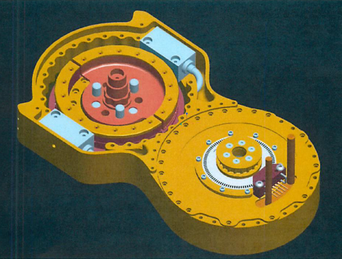
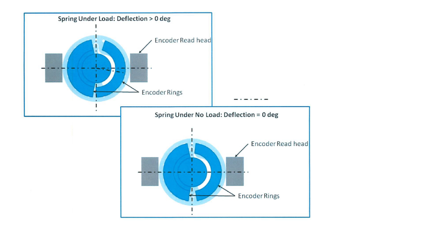
The SRTS enables measurement of position, velocity, and torque of a rotating system (e.g., actuator, motor, crankshaft, rotor, etc.) using two optical sensors and a single, custom-designed split-ring rather than the standard dual-ringed systems commonly used for similar applications. The split-ring is comprised of two structural arcs positioned in a concentric, coplanar relationship, wherein each arc is attached to a component capable of rotation (e.g., a lower leg and upper leg, where the SRTS acts as a knee). The two arcs contain indications or codes on their outer surfaces that are read by the optical sensors to determine the relative deflection of the structural arcs as they rotate.
The SRTS configuration discussed above is limited to 180-degree applications. The addition of a third structural arc and a third optical reader, however, would enable 360-degree functionality.
Tests have shown the SRTS has a high degree of tolerance to temperature differences and provides higher resolution measurements than competing technologies.


Benefits
- Enables lower profile and lower weight: similar technologies use stacked rotary position sensors, resulting in increased volume and stack height - SRTS enables systems to be thinner and lighter
- Offers greater accuracy: SRTS offers highly accurate position measurement and displacement measurement
- Provides an adaptable system: the split-ring design may also be employed in various configurations with different devices or sensors
Applications
- Robotics
- Medical fields including prosthetics
- Aerospace & Defense
- Automotive
- Testing & Measurement
- Industrial Tools and Machinery
|
Tags:
|
|
|
Related Links:
|
Similar Results

Space Suit RoboGlove (SSRG)
NASA is currently developing the next generation space suit for future missions, including the optimization of space suit gloves. When non-assisted space suit gloves are coupled to a pressurized suit and operated in a vacuum, they tend to limit the range of motion of an astronaut's hand to as little as 20% of normal range. Many of NASA's future missions will be in challenging environments where an astronaut’s hand dexterity will be critical for the success of NASA missions. Innovators at JSC have improved the performance on the second-generation, robotically assisted SSRG, to reduce exertion and improve the hand strength and dexterity of an astronaut in situ.
The SSRG’s system detects user finger movements using string potentiometers and contact with objects using force-sensitive resistors (FSRs). FSRs are imbedded in the distal and medial phalanges, palmar side of the glove. To move a finger, an actuator pulls a tendon through a Bowden Cable system which transfers mechanical pulling force of an inner cable relative to a hollow outer cable, like the brakes on a bicycle, as seen in the Figure below. An improved controller commands the new, more powerful linear actuator to drive tendon operation while minding custom controller parameters inputted through a digital editor tool.
The Space Suit RoboGlove is at TRL 6 (system/subsystem model or prototype demonstrated in a relevant environment) and it is now available for licensing. Please note that NASA does not manufacture products itself for commercial sale.

Upper Body Robotic Exoskeleton
NASA's soft, portable, wearable robotic device is "plug and play" - it includes all necessary electronics, actuation, software, and sensors required to achieve augmented limb movement. The garment is designed such that the human-robot interface distributes load across the torso, maximizing user comfort. Donning and doffing is simple, as the device lowers over the head, straps to the torso via Velcro, and possesses adjustable custom arm cuffs. Actuators are housed in the back of the garment, which pull custom conduit-tendon-based systems attached to the limb at optimized locations, causing the joint of interest to move to the specified orientation. Force sensing is employed to enable optimal control of the limb, measuring user-applied force to maintain commanded joint orientations. Integrated electronics and software provide power distribution, safety monitoring, data transfer and data logging.
NASA's garment has multiple modes of operation. In active assist mode, shoulder abduction and flexion, and elbow flexion, may be commanded either simultaneously via coordinated control or individually while holding position/orientation of the other joints. In passive assist mode, the user can freely move the limb while the system provides minimal torque to the shoulder and elbow.
The upper body robotic exoskeleton is at a TRL 6 (system/subsystem prototype demonstration in a relevant environment) and it is now available for your company to license and develop into a commercial product. Please note that NASA does not manufacture products itself for commercial sale.

Foot Pedal Controller
The Foot Pedal Controller enables an operator of a spacecraft, aircraft, or watercraft, or a simulation of one in a video game, to control all translational and rotational movement using two foot pedals. This novel technology allows control across all six degrees of freedom, unlike any technology on the market. The components of the technology are a support structure, a left foot pedal, a right foot pedal, and supporting electronics. The Foot Pedal Controller is intuitive, easy to learn, and has ergonomic features that accommodate and stabilize the operator's feet. A working prototype is available to demonstrate key technology features to potential licensees.
The Foot Pedal Controller technology could be used in designs for the flight deck of the future, video game controls, drone operations and flight simulators. This technology can be useful in any application where it is preferred or desirable to use the feet to control motion rather than using the hands. A potential market could be foot control of equipment by people with arm or hand disabilities. A unique aspect of the innovation is the consideration of natural foot mechanics in the design and placement of the sensors and actuators to reduce operator fatigue. The axes of rotation of the Controller align with the joints of the foot so the foot moves naturally to control the movement of the craft. NASA seeks collaborations with companies interested in licensing and partnering to further develop and commercialize the technology.

Pressure Sensor Mechanism
In operation, this RFID-enabled patented technology reacts to a pressure change causing the passive tag to generate an electromagnetic field. The RFID pressure sensor/passive tag reacts to the electromagnetic field and responds by sending a signal to an interrogator. The interrogator receives the reflected signal, measures the returned signal strength indications ("RSSI") of the reflected signal and sends the RSSI measurements and identification of the responding RFID sensors to the processor to determine the pressure. Potential applications for this technology include remote patient mobility monitoring, robotic control systems, and pressure sensing gloves. Older devices may also be outfitted with these sensors to add pressure-monitoring functionality while avoiding the cost of a total system replacement.

Advanced Humanoid Robotic Arm Technologies
R2 uses brushless DC motors, harmonic drive gear reductions, and electromagnetic failsafe brakes as the building blocks for the powerful, torque-dense actuators in its human-scale, 5 DoF upper arms. Moreover, the use of series elastic actuators and novel tension sensing & control systems represent some of the most innovative technologies present in the humanoid robotic arms of R2.
Series Elastic Actuators (SEAs): R2’s SEAs achieve fine torque sensing at each of its joints without sacrificing strength or payload capacity. Such capabilities are enabled through the development of several advanced technologies. Specifically, novel planar torsion springs (U.S. Patent No. 8,176,809) are integrated into each rotary series elastic actuator (U.S. Patent No. 8,291,788), while two absolute angular position sensors, calibrated using a novel technique (U.S. Patent No 8,250,901), measure the deflection of each spring. Force and Impedance Control Systems (U.S. Patent No. 8,525,460): These systems use position sensor signals for sending position data to an embedded processor that determines the positional orientation of the load relative to a motor shaft and its related torque on a string. A FPGA-based controller (U.S. Patent No. 8,442,684) provides a high-speed (10 KHz) control loop for the electric motor and gear reduction assembly present in R2 joints.
Tension Sensing & Control of Tendon-Based Robotic Manipulators: NASA has also developed technologies to provide tension sensing & control of humanoid robotic arms. First, a tendon tension sensor (U.S. Patent No. 8,371,177) measures strain on tendons (strings) employed in robotic arms. A novel calibration system (U.S. Patent No. 8,412,378) calibrates the tendon tension sensors. Finally, joint space impedance control systems (U.S. Patent Nos. 8,170,718 & 8,060,250) provide closed-loop control of joint torques or joint impedances without inducing dynamic coupling between joints, as well as programmable Cartesian arm stiffness.


