Search
PATENT PORTFOLIO
Propulsion
NASA researchers have a long history of developing innovative solutions for the generation and management of thrust, including rocket engines, ion engines, and other advanced propulsion systems. Whether you're looking to improve the efficiency of aircraft engines or to develop new rocket propulsion systems, NASA's propulsion technology portfolio is sure to contain something of interest.
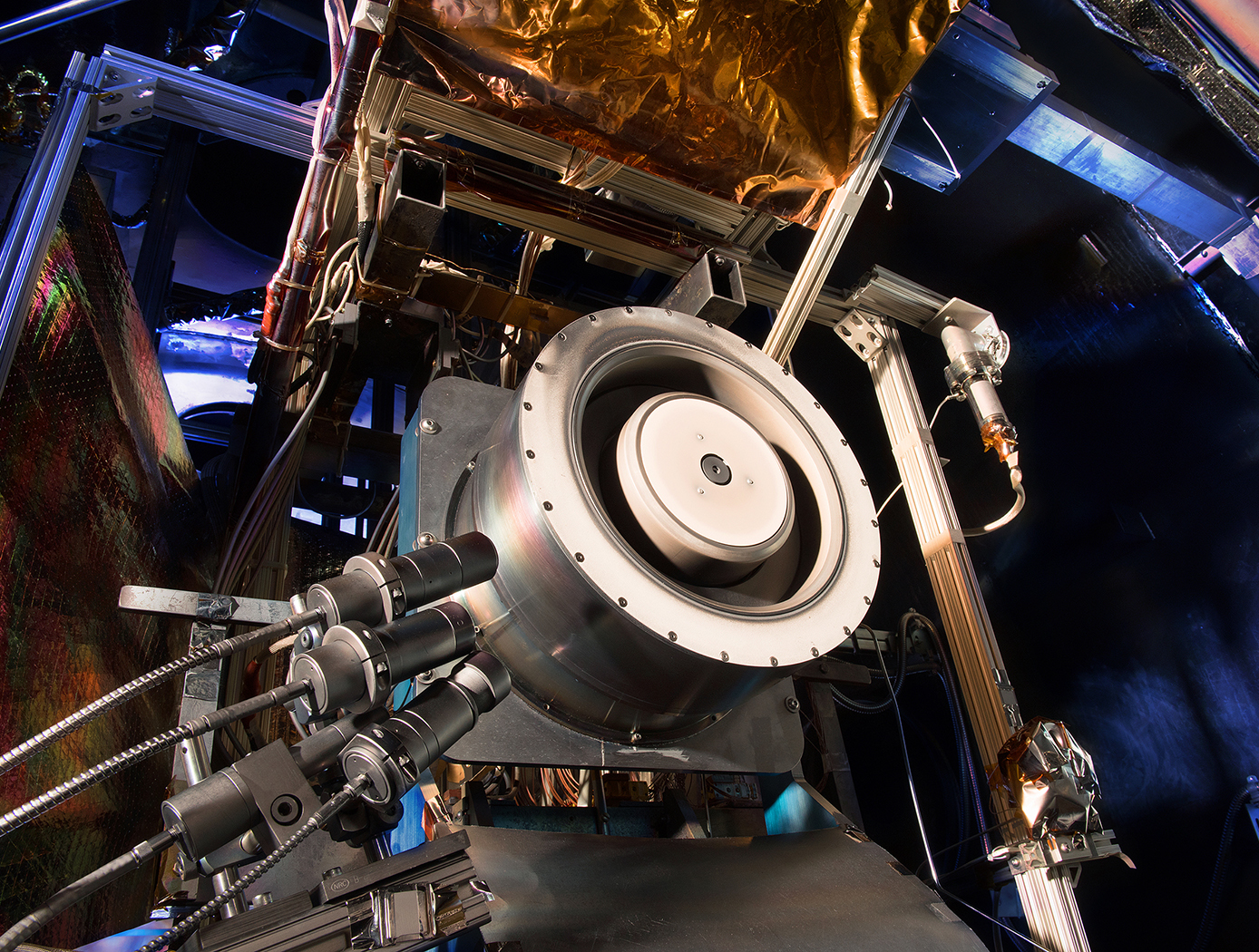
Hall Effect Thruster Technologies
Used for propelling Earth-orbiting satellites and deep-space robotic vehicles, the HET gets its name because it traps electrons with an intense radial magnetic field in an azimuthal Hall current moving around the circumference of an annular ceramic channel. The electrons in the circulating Hall current ionize the onboard propellant - the inert gas xenon - and create an ionized plasma. The xenon plasma is then accelerated axially, via an applied electric field along the coaxial channel, to an exit velocity of up to 65,000 miles per hour to produce thrust. The interaction of the accelerated plasma and the downstream edge of the channel, where the plasma is the most energetic, results in erosion of the surrounding magnetic system used to generate the plasma. One of NASA Glenn's novel designs relies on an azimuthally symmetric configuration that minimizes radial magnetic fields at the discharge chamber walls. This configuration completely shields the walls of the discharge chamber from the high-energy plasma ions. With regard to the discharge-channel-wall replacement innovation, an actuator can be configured to extend the discharge chamber along the centerline axis. The actuator can be either mechanical or programmable. In either case, the sleeve can be extended while an upstream portion of the discharge chamber remains stationary, thereby preventing plasma exposure. These novel designs increase the efficiency and extend the lifetime of the HET to five times that of unshielded thrusters, enabling a new era of space missions.

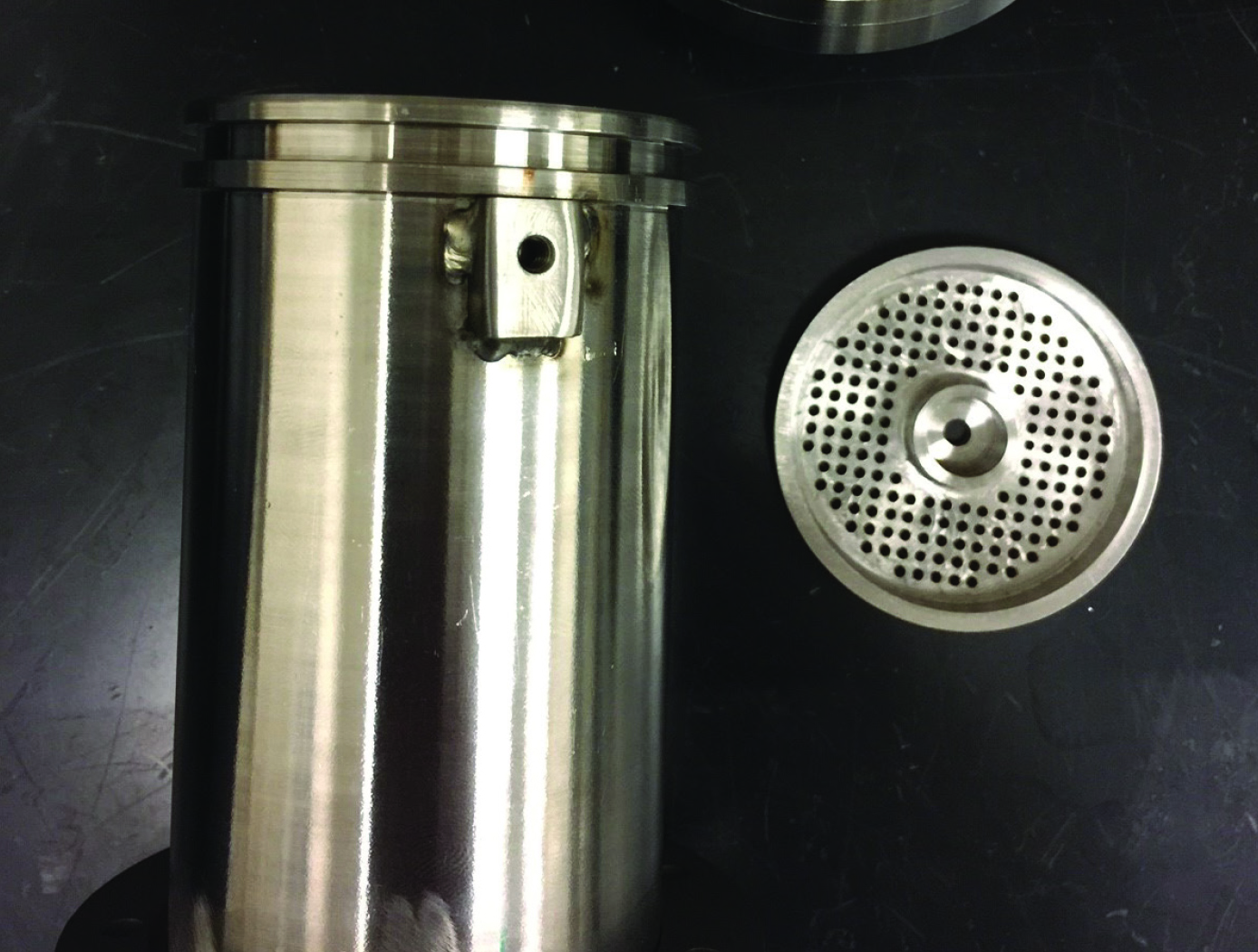
HYPERFIRE
In order to maintain the low cost, simplicity, and quick turnaround of cold-flow testing while improving accuracy, NASA evaluated unconventional gases for use as simulants. During such evaluations, NASA discovered that by adjusting stagnation temperature, the isentropic exponent of ethane can be tuned to approximate those of common rocket propellants (e.g., hydrogen, hypergols, alcohols, and hydrocarbons). Furthermore, due to ethanes high auto-ignition temperature and resistance to condensation, tuned ethane enables testing of expansion ratios much larger than conventional inert-gas testing.
To leverage this discovery, NASA developed a hardware-based system to treat ethane and obtain nozzle chamber conditions that match the appropriate aerodynamics for a specific test. The system, named HYPERFIRE, works in the following manner. Liquid ethane is transferred to a piston-style run tank, where it is pressurized. Then, the ethane is run through two insulated pebble beds where it is heated, vaporized, and stabilized. Finally, the treated ethane is transferred from the second pebble bed to a small thrust takeout structure, and through the test article. Control of valves and regulators is managed by an onboard computer, accessed via a LabVIEW™ interface. The system is mounted on a hurricane-resistant steel frame to enable transportation via forklift.
Heated ethane reproduces the aerodynamics of combustion products at low temperatures relative to alternative testing methods. Thus, test articles can be manufactured using low-cost, low temperature rated, transparent materials (e.g., acrylic). In addition to reducing testing cost, this grants optical access to internal flowfields, enabling advanced diagnostic techniques (e.g., Schlieren imaging, particle image velocimetry) not possible with hot-fire testing and less meaningful with conventional cold-flow testing.
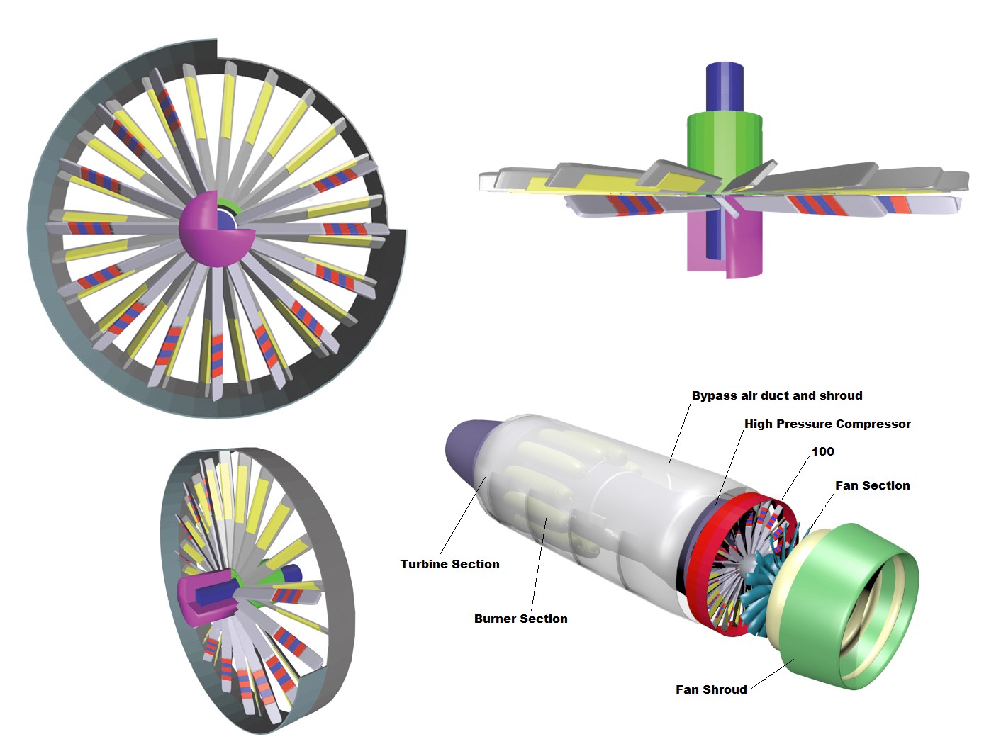
Axial Magnetic Flux Airflow Integrated Compressor-Generator-Motor Turbojet
The innovation uses the rotating blades of the compressor section to act as structural support for the generator. Since the compressor is the coolest part of the engine, it will reduce the potential for interference with magnetics and associated curie points of the permanent magnets. The placement of the generator in the cooler part of the engine flowpath (fan or compressor) will also improve the electrical insulation system's degradation and serve to improve overall system lifetime.
The configuration proposed by Armstrong's design would be an axial magnetic flux permanent magnet generator or motor. The electrical/mechanical interface could serve to deliver power to the shaft of the turbojet/fan or extract power from the shaft.
This axial electromagnetic flux design is more efficient for the combined function of aero-thermal heat transfer and generation of electricity. This is due to the relative amount of available cooling surface area, which has an advantage over radial designs given the total system volumetric aspect ratio of the generator/compressor section. When the system is viewed as a thermodynamic cycle, it is more efficient because it is essentially a regenerative cycle, with the heat of generation being fed back into the cycle instead of being released into the ambient surroundings
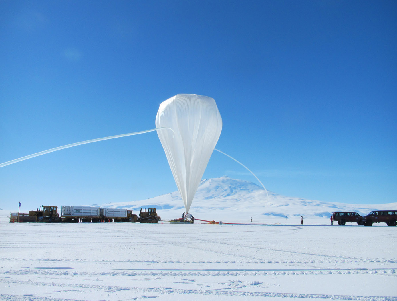
Standardized Coarse Azimuth Pointing System
The Standardized Coarse Azimuth Pointing System is a system for any balloon-borne platform with a suspended payload that was less than 5,500 lbs. It separates the rotation of the gondola and the payload from the balloon. The rotator utilizes GPS and solar sensors for command orientation of the payload. There are solar sensors at the top of the rotator providing a 360-degree view. A guidance, navigation, and control system commands sensors to look at a specific point. For example, sensors can detect the position of the sun. The sensor command is sent through the avionics packages on board to start the motor and turn the shaft until the sensors send feedback that they are at the commanded position. The rotator holds the payload at that position until commanded otherwise. The rotator is designed to have a 5 arc-minute pointing capability, and it has demonstrated a 1.4 arc-minute accuracy. The motor runs on a 28V battery source. The system is designed to be operational in a thermal range of -80 degrees Celsius to +50 degrees Celsius. The system can also accommodate the option of integrating a slip ring with 20 separate channels for power, DSL link, and AART communications.
The Standardized Coarse Azimuth Pointing System features a hollow titanium shaft, 3-D printed solar sensor mounts, 3-D printed avionics package mounts, and a custom motor frame mount. The system also utilizes 3-D printed templates to standardize the assembly of both rotators, so that nonuniform match drilling is not a problem.
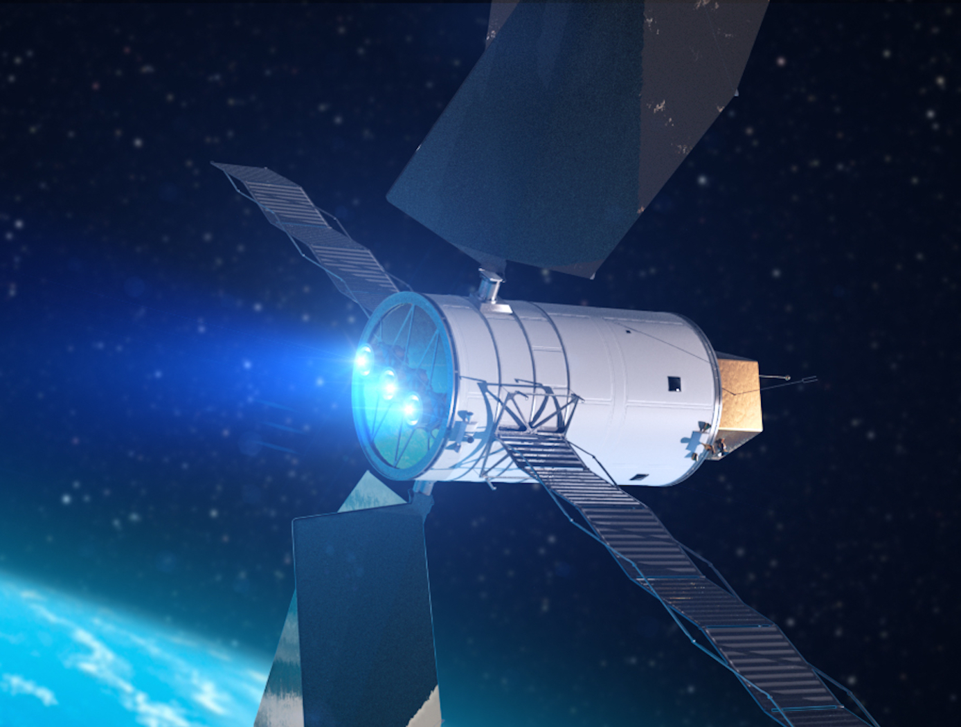
Sublimable Propellant Source for Iodine-fed Ion Propulsion System
NASAs iodine vapor feed system is based on a mechanism that holds and maintains the solid iodine is contact with a heated surface, in this case the walls of the propellant tank. The mechanism provides a robust and reliable steady-state delivery of sublimated iodine vapor to the ion propulsion system by ensuring good thermal contact between the solid iodine and the tank walls.
To date, the technology development effort includes extensive thermal, mechanical and flow modelling together with testing of components and subsystems required to feed iodine propellant to a 200-W Hall thruster. The feed system has been designed to use materials that are resistant to the highly-reactive nature of iodine propellant. Dynamic modeling indicates that the feed system tubing can be built is such a way as to reduce vibrationally-induced stresses that occur during launch. Thermal modeling has been performed to demonstrate that the feed system heater power levels are sufficient to heat the tank and propellant lines to operating temperatures, and sublime the iodine in the storage tank to supply propellant for reliable and long-term operation.
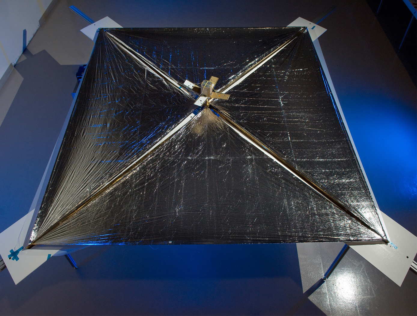
SMART Solar Sail
The SMART solar sail includes a reflective film stretched among nodes of a SMART space frame made partly of nanotubule struts. A microelectromechanical system (MEMS) at each vertex of the frame spools and unspools nanotubule struts between itself and neighboring nodes to vary the shape of the frame. The MEMSs is linked, either wirelessly or by thin wires within the struts, to an evolvable neural software system (ENSS) that controls the MEMSs to reconfigure the sail as needed. The solar sail is highly deformable from an initially highly compressed configuration, yet also capable of enabling very fine maneuvering of the spacecraft by means of small sail-surface deformations. The SMART Solar Sail is connected to the main body of the spacecraft by a SMART multi-tether structure, which includes MEMS actuators like those of the frame plus tethers in the form of longer versions of the struts in the frame.
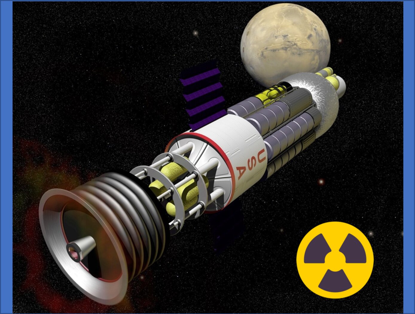
Improved Efficiency in Nuclear Propulsion
Current nuclear propulsion technologies do not utilize the additional energy expelled as gamma ray radiation during nuclear fission. This results in the loss of 6.5% of the total fission energy, which could be used to improve propulsion capabilities. The NTAC Augmented Nuclear Electric Propulsion and/or Nuclear Thermal Propulsion design is more efficient than existing technology and captures an additional 6.5% (13.3 MeV) of radiation energy that is currently lost to radiation shielding. In this design the NTAC cell structure surrounds the TRISO (TRi-structural ISOtropic particle fuel) bead-filled rocket chamber, covering all sides and the top of the chamber, therefore capturing additional energy. This structure allows one-way energy flow to then be expelled through the bottom cavity as exhaust gas
This technology is lower weight and less elaborate than current radiation shielded-propulsion systems. Equipping nuclear spacecraft systems with the NTAC Augmented Nuclear Electric Propulsion and/or Nuclear Thermal Propulsion design could reduce travel time to Mars by 50%. It has lower radar signatures compared to solar panels and could be used for systems that need to fly undetected, such as Earth observing satellites. Additionally, it has a lower noise output, which could have applications in reducing noise from submarine and aircraft carrier power systems.
Power Processing Unit (PPU) for Small Spacecraft Electric Propulsion
Key subsystems of a scalable PPU for low-power Hall effect electric propulsion have been developed and demonstrated at NASA GRC. The PPU conditions and supplies power to the thruster and propellant flow control (PFC) components. It operates from an input voltage of 24 to 34 VDC to be compatible with typical small spacecraft with 28 V unregulated power systems. The PPU provides fault protection to protect the PPU, thruster, PFC components, and spacecraft. It is scalable to accommodate various power and operational requirements of low-power Hall effect thrusters. An important subsystem of a PPU is the discharge supply, which processes up to 95% of the power in the PPU and must process high voltage to accelerate thrust generating plasma. Each discharge power module in this PPU design is capable of processing up to 500 W of power and output up to 400 VDC. A full-bridge topology operating at switching frequency 50 kHz is used with a lightweight foil transformer. Two or more modules can operate in parallel to scale up the discharge power as required. Output voltage and current regulation controls allow for any of the common thruster start-up modes (hard, soft or glow).
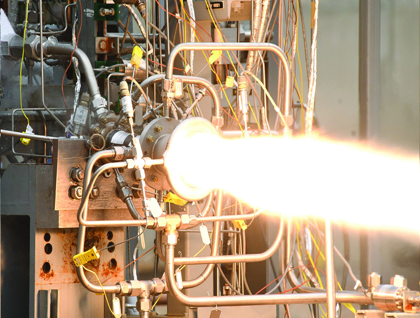
A One-piece Liquid Rocket Thrust Chamber Assembly
The one-piece multi-metallic composite overwrap thrust chamber assembly is centrally composed of an additively manufactured integral-channeled copper combustion chamber. The central chamber is being manufactured using a GRCop42 or GRCop84 copper-alloy additive manufacturing technology previously developed by NASA. A bimetallic joint (interface) is then built onto the nozzle end of the chamber using bimetallic additive manufacturing techniques. The result is a strong bond between the chamber and the interface with proper diffusion at the nozzle end of the copper-alloy. The bimetallic interface serves as the foundation of a freeform regen nozzle. A blown powder-based directed energy deposition process (DED) is used to build the regen nozzle with integral channels for coolant flow. The coolant circuits are closed with an integral manifold added using a radial cladding operation. To complete the TCA, the entire assembly including the combustion chamber and regen nozzle is wrapped with a composite overwrap capable of sustaining the required pressure and temperature loads.
View more patents

