Search
Robotics Automation and Control
Assemblers
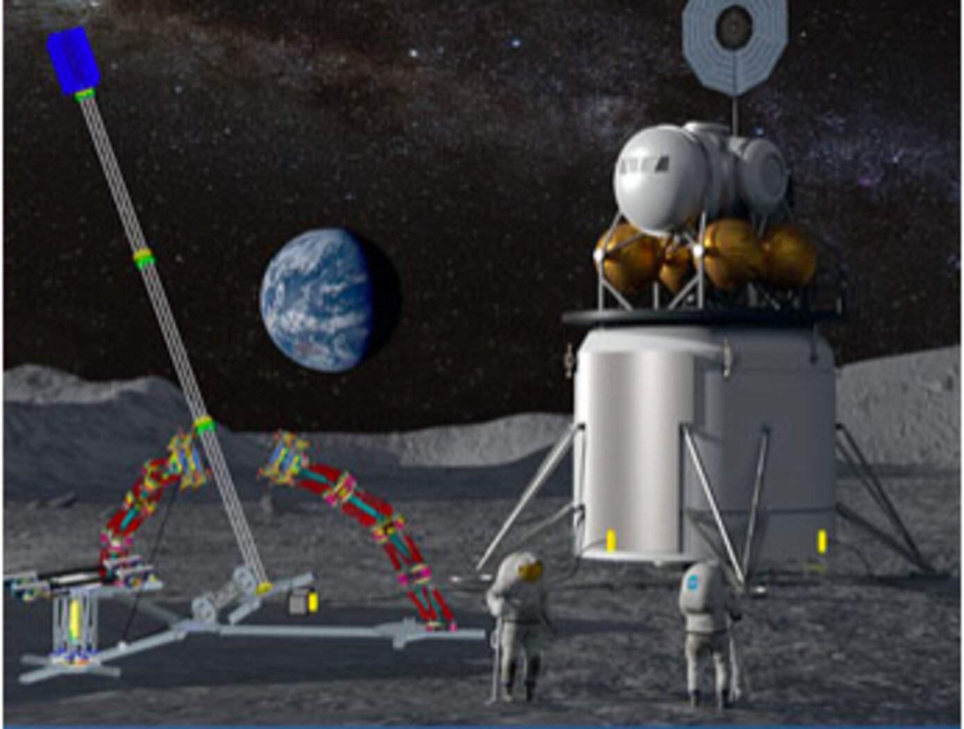
Assemblers are a team of modular robots that work together to build things. Each Assembler is a stack of one or more Stewart platforms, or hexapods, made up of two plates connected by six linear actuators for movement, enabling a full six-degree-of-freedom (DOF) pose of the top plate relative to the bottom plate (see figure to the right). An end effector on each Assembler enables gripping, lifting, and welding/joining. The Assemblers system architecture features novel control algorithms and software, sensors, and communicator technology that coordinate operations of Assembler teams. The control system includes an important module for task management that estimates how many robots are needed, the optimal number of hexapods in each Assembler, and the estimated voltage needed. There are also modules for trajectory generation, joint control, sensor fusion, and fault detection. The novel control system directs the Assembler operations for high accuracy and precision, yet there is built-in dynamic resilience to failure. For example, if a single hexapod on an Assembler fails, the system deems it “rigid” in its last pose and redistributes the work to the other Assemblers.
The image below shows a storyboard of operations for how Assemblers might build a solar array. NASA has developed a hardware demo with communications between subsystems, backed up by detailed simulations of the kinematics and actuator dynamics.
Information Technology and Software
Near-Real Time Verification and Validation of Autonomous Flight Operations
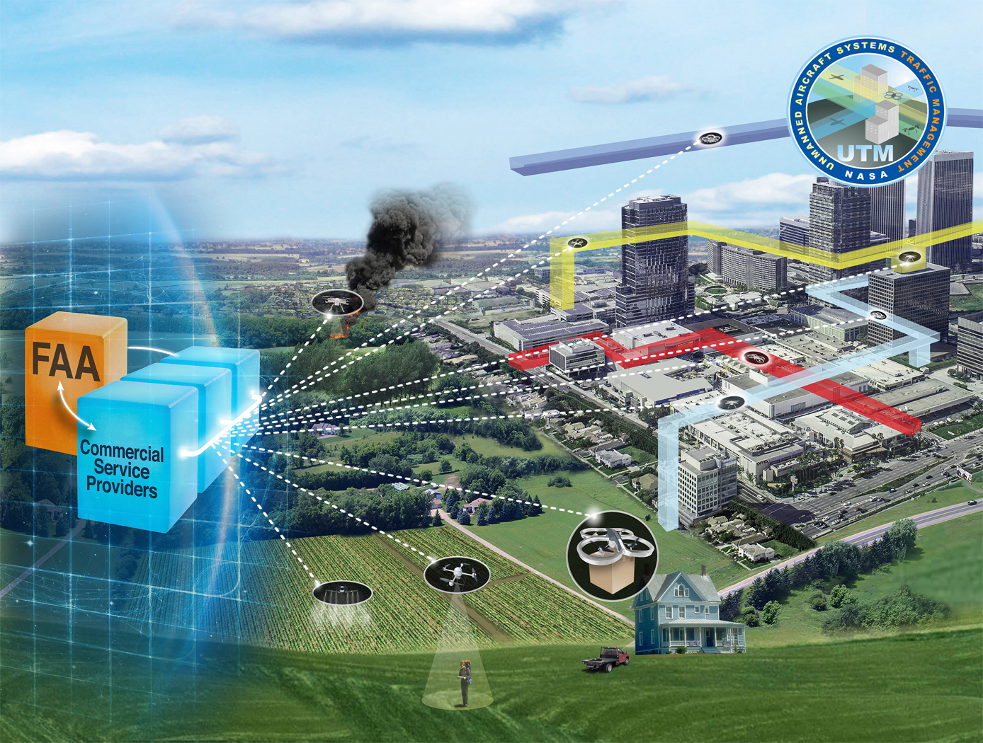
NASA's Extensible Traffic Management (xTM) system allows for distributed management of the airspace where disparate entities collaborate to maintain a safe and accessible environment. This digital ecosystem relies on a common data generation and transfer framework enabled by well-defined data collection requirements, algorithms, protocols, and Application Programming Interfaces (APIs). The key components in this new paradigm are:
Data Standardization: Defines the list of data attributes/variables that are required to inform and safely perform the intended missions and operations.
Automated Real Time And/or Post-Flight Data Verification Process: Verifies system criteria, specifications, and data quality requirements using predefined, rule-based, or human-in-the-loop verification.
Autonomous Evolving Real Time And/or Post-Flight Data Validation Process: Validates data integrity, quantity, and quality for audit, oversight, and optimization.
The verification and validation process determines whether an operation’s performance, conformance, and compliance are within known variation. The technology can verify thousands of flight operations in near-real time or post flight in the span of a few minutes, depending on networking and computing capacity. In contrast, manual processing would have required hours, if not days, for a team of 2-3 experts to review an individual flight.
sensors

More Reliable Doppler Lidar for Autonomous Navigation
The NDL uses homodyne detection to obtain changes in signal frequency caused by a target of interest. Frequency associated with each segment of the modulated waveform collected by the instrument is positive or negative, depending on the relative range and direction of motion between the NDL and the target. Homodyne detection offers a direct measurement of signal frequency changes however only the absolute values of the frequencies are measured, therefore additional information is necessary to determine positive or negative sign of the detected frequencies. The three segmented waveform, as opposed to conventional two-segmented ones, allows for resolving the frequency sign ambiguity. In a practical system, there are times when one or more of the three frequencies are not available during a measurement. For these cases, knowledge of the relative positions of the frequency sideband components is used to predict direction of the Doppler shift and sign, and thus make correct range and velocity measurements. This algorithm provides estimates to the sign of the intermediate frequencies. The instrument operates continuously in real time, producing independent range and velocity measurements by each line of sight used to take the measurement. In case of loss of one of the three frequencies, past measurements of range and velocity are used by the algorithm to provide estimates of the expected new range and velocity measurement. These estimates are obtained by applying an estimation filter to past measurements. These estimates are used during signal loss to reduce uncertainty in the sign of the frequencies measured once signals are re-established, and never to replace value of a measurement.
Mechanical and Fluid Systems
Extractor for Chemical Analysis of Lipid Biomarkers in Regolith (ExCALiBR)
The technology provides miniaturized techniques for extracting trace amounts of organic molecules (lipids) from natural samples. It operates as an autonomous, miniaturized fluidic system, integrating lab techniques for lipid analysis while minimizing reagent volumes and concentrating organics for analysis, thereby increasing signal-to-noise ratios by orders of magnitude. The non-aqueous fluidic system described herein for astrobiological and life-detection missions (either in situ or returned sample) is configured to extract lipid organics from regolith using (1) a fluidic sample processor made of materials compatible with organic solvents and (2) a machine-learning system to select processing steps and parameters to maximize lipid yield. A critical gap is bridged by integrating technologies into a system that replicates analytical lab procedures autonomously on a spaceflight instrument scale with fidelity to original lab techniques. Automated fluidic devices combine controlled handling of liquids with sequential operations and parallelization of replicate processes. By designing such systems to closely interface with both sample-delivery and analytical measurement systems, laboratory analyses are automated. The technology adapts best practice laboratory methods for lipid analysis, overcoming analytical challenges like low organic abundance, interference of minerals/salts, and degradation of origin-diagnostic molecular structures. The extraction and concentration techniques from rock/soil samples can be applied to any biomarkers by changing the solvent, temperature, and agitation.
Sensors

RFID Tags Collaborate for Data Retrieval
Commonly used RFID protocols are widely accepted because they are inexpensive and easy to implement. However, the associated low transmit power and narrow bandwidth typically result in coarse local-ization estimates. Often it is desirable to know the precise location of assets without reverting to an entirely different and more expensive protocol. Additionally, many industrial and other applications may desire technology that confirms the mating of components. This new program-mable sensor tag technology facilitates both precise localization and mating confirmation in-part by allowing the RFID sensor tag to become a type of distributed low-cost reader.
To determine a tag attachment, this innovation utilizes a fixed location RFID sensor tag that incorporates a receptacle node to measure an electrical “influence” through resistance, capacitance, inductance, etc. Assets for which localization is desired are outfitted with “influence tags” – devices that produce a set of distinguishable responses when placed in the receptacle region of the RFID sensor tag. Mating or connections are confirmed when electrodes from an influence tag become attached to matching electrodes on a sensor tag’s receptacle node. Information obtained by the RFID sensor tag is stored in its local memory bank through which a dedicated reader can retrieve influence tag information.
Potential applications exist for this technology where specific assets need to be precisely located and/or confirmation is needed when two parts have been correctly connected or attached. This RFID tag technology allows the retrieval of inventory status information in an energy efficient manner from inexpensive, small form factor hardware. Robotic retrieval of assets can be more easily facilitated with this innovation.
Robotics Automation and Control
Advanced Humanoid Robotic Hand Technologies
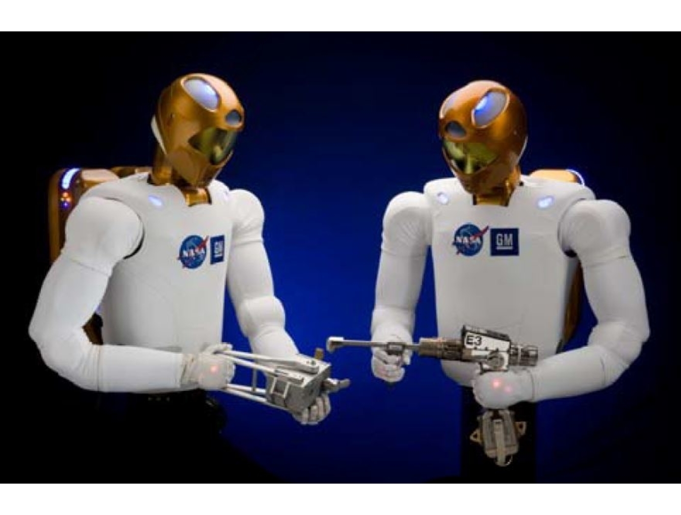
The R2 hand and forearm assembly represents the cutting edge of humanoid robotics technologies. The highly modular design provides significant improvements over prior humanoid robotic hands, especially in the areas of strength, speed, sensing, and ability to approximate human grasps.
<i>Hand, Finger, and Wrist Assembly Design:</i> The robotic humanoid lower arm design (U.S. Patent No. 9,505,134) includes novel robotic finger (U.S. Patent No. 8,562,049), thumb (U.S. Patent No. 8,424,941), and wrist (U.S. Patent No. 8,498,741) assemblies.
<i>Actuation & Control System:</i> A novel finger actuation system (U.S. Patent No. 8,467,903) – comprised of an actuator, tendon, conduit, tension sensor (U.S. Patent No. 8,371,177), and terminator – is perhaps the primary enabling technology for R2’s compact, high performance robotic hand. The actuation system is packaged in the wrist (U.S. Patent No. 8,401,700) and reduces the number of actuators, providing significant space savings. Control systems include methods for tensioning (U.S. Patent Nos. 8,412,376, 8,618,762, & 8,056,423) and controlling torque (U.S. Patent No. 8,565,918) of the tendon-driven robotic fingers. The finger actuation control system (U.S. Patent No. 8,489,239) can operate using force- or position-based control laws.
<i>Tactile System:</i> R2’s hands feature an innovative tactile system that grant the robot a sense of touch (e.g., measurement of external contact forces, shear force, and slippage of objects held in the hand) – an important requirement for robots designed to perform complex tasks in an automated fashion. The tactile system is enabled by novel six degree of freedom (DoF) force torque sensors (U.S. Patent No. 7,784,363), three of which are integrated into the fingers (at the proximal, medial, and distal phalanges) and two in the thumb (medial and distal phalanges). A calibration system (U.S. Patent No. 8,265,792) ensures the sensors maintain high accuracy throughout operation.
<i>Autonomous Grasping:</i> A novel grasp assist device (U.S. Patent No. 9,878,452 & 9,067,319) enables reliable, autonomous interaction with a broad range of objects (e.g., tools). A particle filter-based contact state estimation device (U.S. Patent No. 8,280,837) performs object localization and characterization.
aerospace
Spacecraft to Remove Orbital Debris
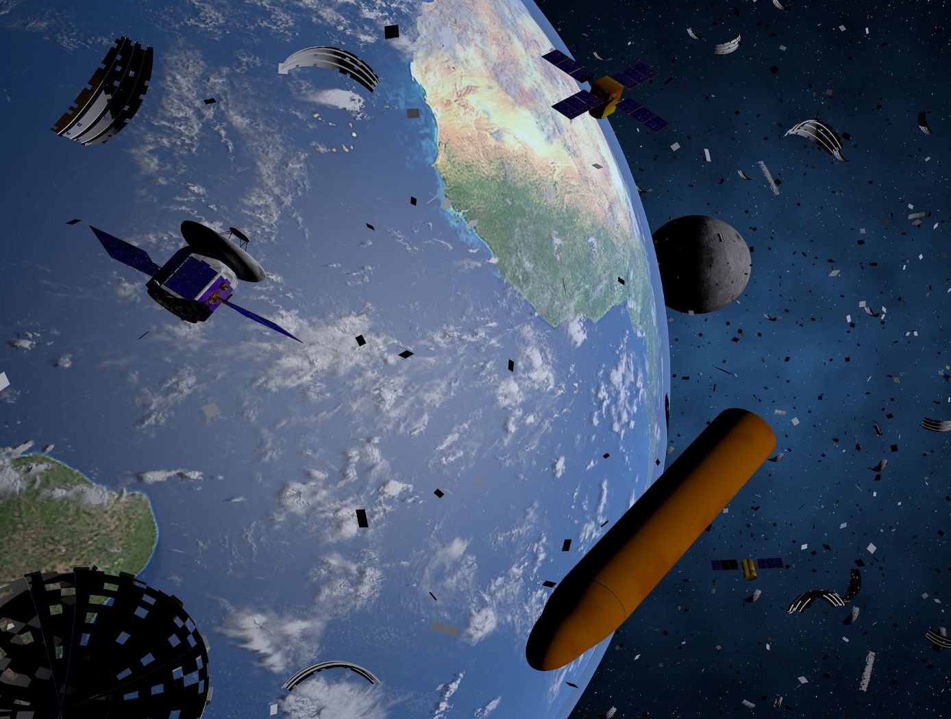
An approach to mitigating the creation of additional orbital debris is to remove the sources of future medium debris by actively removing large spent objects from congested orbits. NASA has introduced the ADRV, an efficient and effective solution to remove large debris from LEO such as spent rocket bodies and non-functional satellites. The concept yields a single use, low-cost, lightweight, high mass fraction vehicle that enables the specific removal of large orbital debris (1000 - 4000 kg mass, 200 - 2000 km altitude, and 20 98-degree inclination). The ADRV performs rendezvous, approach, and capture of non-cooperative tumbling debris objects, maneuvering of the mated vehicle, and controlled, targeted reposition or deorbit of the mated vehicle. Due to its small form factor, up to eight ADRVs can be launched in a single payload, enabling high impact orbital debris removal missions within the same inclination group.
Three key technologies were developed to enable the ADRV: - 1) The spacecraft control system (SCS) is a guidance, navigation, and control system that provides vehicle control during all phases of a mission; - (2) The debris object characterization system (DOCS) characterizes movement and capture of non-cooperative targets; and - (3) The capture and release system (CARS) allows the vehicle to capture and mate with orbital debris targets. These technologies can improve the current state-of-the-art capabilities of automated rendezvous and docking technology significantly for debris objects with tumbling rates up to 25 degrees per second. This approach leverages decades of spaceflight experience while automating key mission areas to reduce cost and improve the likelihood of success.
manufacturing
Fully Automated High-Throughput Additive Manufacturing
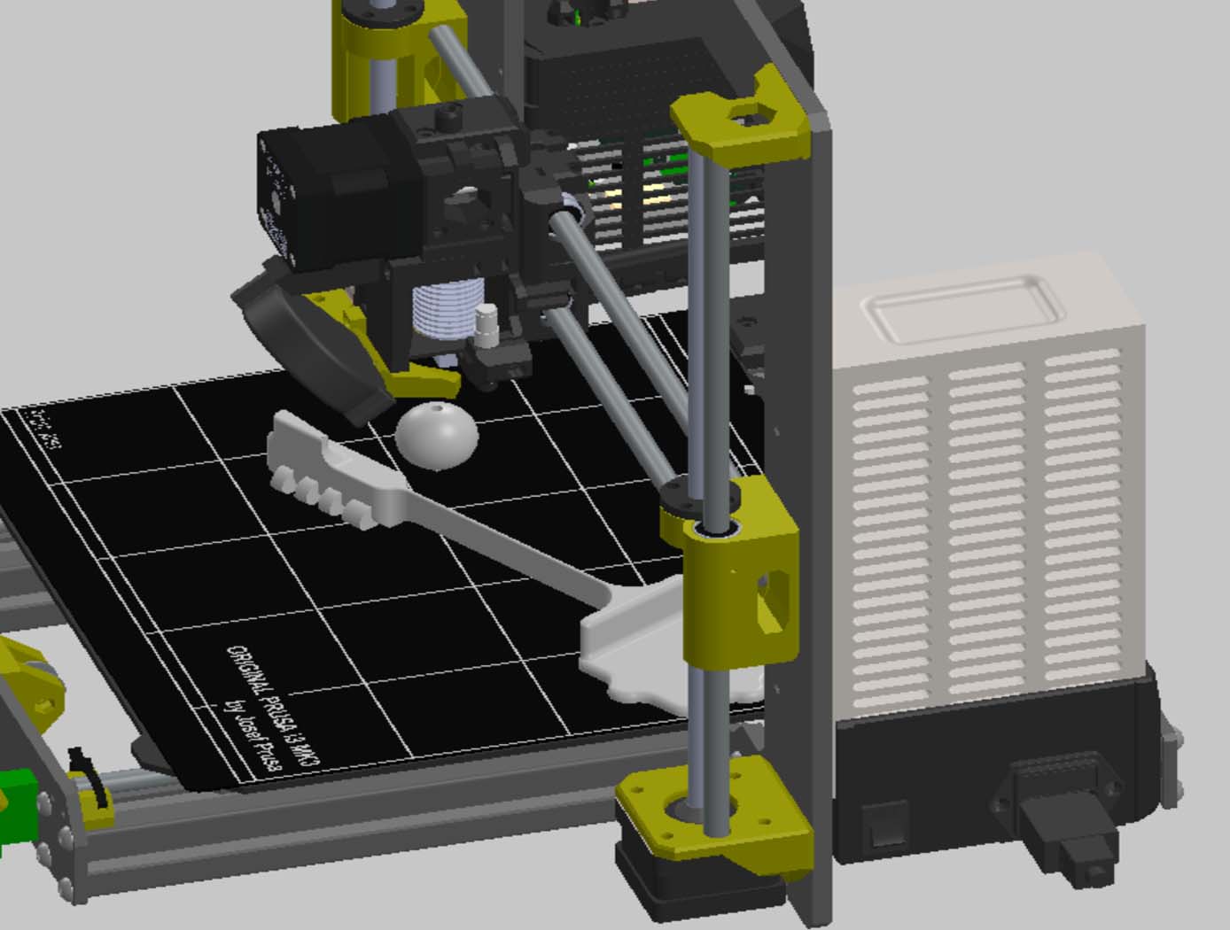
The technology is a method to increase automation of Additive Manufacturing (AM) through augmentation of the Fused Filament Fabrication (FFF) process. It can significantly increase the speed of 3D printing by automating the removal of printed components from the build platform without the need for additional hardware, which increases printing throughput. The method can also be leveraged to perform automated object testing and characterization. The method includes embedding into the manufacturing instructions methods to fabricate directly onto the build platform an actuator tool, such as a linear spring. The deposition head can be leveraged as a robotic manipulator of the actuator tool to bend, cock, and release the linear spring to strike the target manufactured object and move it off the build platform of the machine they were manufactured on. The ability for an object to 'fly off of the machine that made it' essentially enables automated clearing of the processed build volume. The technology can also be used for testing the AM machine or the feedstock material by successively fabricating prototypes of the manufactured object, and taking measurements from sensors as the actuator strikes the prototype. This provides automated testing for quality control, machine calibration, material origins, and counterfeit detection.
Optics
3D Lidar for Improved Rover Traversal and Imagery
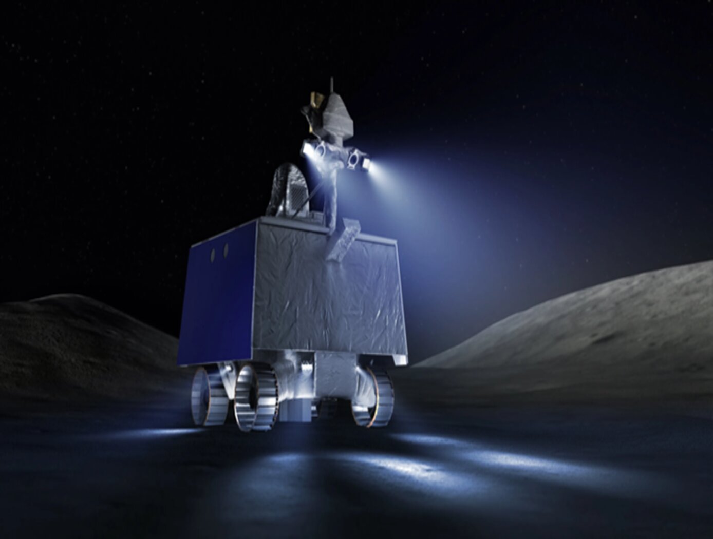
The SQRLi system is made up of three major components including the laser assembly, the mirror assembly, and the electronics and data processing equipment (electronics assembly) as shown in the figure below. The three main systems work together to send and receive the lidar signal then translate it into a 3D image for navigation and imaging purposes.
The rover sensing instrument makes use of a unique fiber optic laser assembly with high, adjustable output that increases the dynamic range (i.e., contrast) of the lidar system. The commercially available mirror setup used in the SQRLi is small, reliable, and has a wide aperture that improves the field-of-view of the lidar while maintaining a small instrument footprint. Lastly, the data processing is done by an in-house designed processor capable of translating the light signal into a high-resolution (sub-millimeter) 3D map. These components of the SQRLi enable successful hazard detection and navigation in visibility-impaired environments.
The SQRLi is applicable to planetary and lunar exploration by unmanned or crewed vehicles and may be adapted for in-space servicing, assembly, and manufacturing purposes. Beyond NASA missions, the new 3D lidar may be used for vehicular navigation in the automotive, defense, or commercial space sectors. The SQRLi is available for patent licensing.
aerospace
Unmanned Aerial Systems (UAS) Traffic Management
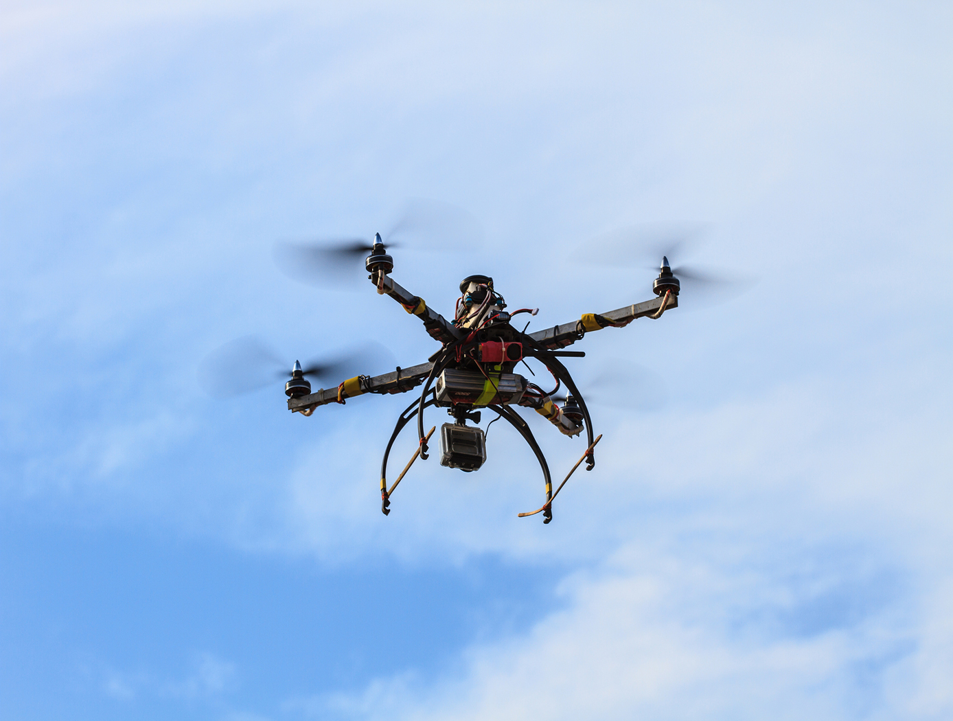
NASA Ames has developed an Autonomous Situational Awareness Platform system for a UAS (ASAP-U), a traffic management system to incorporate Unmanned Aerial Systems (UASs) into the National Airspace System. The Autonomous Situational Awareness Platform (ASAP) is a system that combines existing navigation technology (both aviation and maritime) with new procedures to safely integrate Unmanned Aerial Systems (UASs) with other airspace vehicles. It uses a module called ASAP-U, which includes a transmitter, receivers, and various links to other UAS systems. The module collects global positioning system GPS coordinates and time from a satellite antenna, and this data is fed to the UAS's flight management system for navigation. The ASAP-U module autonomously and continuously sends UAS information via a radio frequency (RF) antenna using Self-Organized Time Division Multiple Access (SOTDMA) to prevent signal overlap. It also receives ASAP data from other aircraft. In case of transmission overload, priority is given to closer aircraft. Additionally, the module can receive weather data, navigational aid data, terrain data, and updates to the UAS flight plan. The collected data is relayed to the flight management system, which includes various databases and a navigation computer to calculate necessary flight plan modifications based on regulations, right-of-way rules, terrain, and geofencing. Conflicts are checked against databases, and if none are found, the flight plan is implemented. If conflicts arise, modifications can be made. The ASAP-U module continuously receives and transmits data, including UAS data and data from other aircraft, to detect conflicts with other aircraft, terrain, weather, and geofencing. Based on this information, the flight management system determines the need for course adjustments and the flight control system executes them for a safe flight route.


