Search
Mechanical and Fluid Systems

Adaptive Camera Assembly
NASA’s adaptive camera assembly possesses a variety of unique and novel features. These features can be divided into two main categories: (1) those that improve “human factors” (e.g., the ability for target users with limited hand, finger, and body mobility to operate the device), and (2) those that enable the camera to survive harsh environments such as that of the moon. Some key features are described below. Please see the design image on this page for more information.
NASA’s adaptive camera assembly features an L-shaped handle that the Nikon Z9 camera mounts to via a quick connect T-slot, enabling tool-less install and removal. The handle contains a large tactile two-stage button for controlling the camera’s autofocus functionality as well as the shutter. The size and shape of the handle, as well as the location of the buttons, are optimized for use with a gloved hand (e.g., pressurized spacesuit gloves, large gloves for thermal protection, etc.). In addition, the assembly secures the rear LCD screen at an optimal angle for viewing when the camera is held at chest height. It also includes a button for cutting power – allowing for a hard power reset in the event of a radiation event. Two large button plungers are present, which can be used to press the picture review and "F4" buttons of the Nikon Z9 through an integrated blanket system that provides protection from dust and thermal environments.
Overall, NASA’s adaptive camera assembly provides a system to render the Nikon Z9 camera (a) easy to use by individuals with limited mobility and finger dexterity / strength, and (b) resilient in extreme environments.
Materials and Coatings

Atomic Layer Deposition-Enhanced Far-to-Mid Infrared Camera Coating
The ALD-Enhanced Far-to-Mid IR Camera Coating is fabricated by first applying a conductively loaded epoxy binder ~500 microns thick onto a conductive metal substrate (e.g., Cu, Al). This serves to provide high absorptance and low reflectance at the longest wavelength of interest, as well as to provide a mechanical buffer layer to reduce coating stress. Borosilicate glass microspheres are coated with a thin film metal via ALD, essentially turning the microspheres into resonators. That film is optically thin in the far infrared and approximates a resistive (~200 ohms per square) coating. Light trapped in the borosilicate glass microspheres is reflected back and forth within the glass–at each contact point, the light is attenuated by 50%. A monolayer of thin metal film-coated borosilicate glass microspheres is applied to the epoxy binder and cured, forming a robust mechanical structure that can be grounded to prevent deep dielectric charging by ionizing radiation in space. Once cured, the far-to-mid IR absorber structure can be coated with a traditional ~20-to-50 microns “black” absorptive paint to enhance the absorption band at short wavelengths, or a “white” diffusive paint to reject optical radiation. At this thickness and broad tolerance, the longwave response of the coating is preserved. Tailoring the electromagnetic properties of the coating layers and geometry enables realization of a broad band absorption response where the mass required per unit area has been minimized.
While NASA originally developed the ALD-Enhanced Far-to-Mid IR Camera Coating for the Stratospheric Observatory for Infrared Astronomy mission, its robustness, absorptive qualities, and optical performance make it a significant addition to IR and terahertz imaging systems. The IR camera coating is at Technology Readiness Level (TRL) 3 (experimental proof-of-concept) and is available for patent licensing.
Optics

Ruggedized Infrared Camera
This new technology applies NASA engineering to a FLIR Systems Boson® Model No. 640 to enable a robust IR camera for use in space and other extreme applications. Enhancements to the standard Boson® platform include a ruggedized housing, connector, and interface. The Boson® is a COTS small, uncooled, IR camera based on microbolometer technology and operates in the long-wave infrared (LWIR) portion of the IR spectrum. It is available with several lens configurations. NASA's modifications allow the IR camera to survive launch conditions and improve heat removal for space-based (vacuum) operation. The design includes a custom housing to secure the camera core along with a lens clamp to maintain a tight lens-core connection during high vibration launch conditions. The housing also provides additional conductive cooling for the camera components allowing operation in a vacuum environment. A custom printed circuit board (PCB) in the housing allows for a USB connection using a military standard (MIL-STD) miniaturized locking connector instead of the standard USB type C connector. The system maintains the USB standard protocol for easy compatibility and "plug-and-play" operation.
optics
Reflection-Reducing Imaging System for Machine Vision Applications
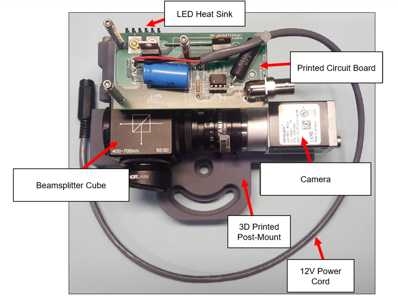
NASAs imaging system is comprised of a small CMOS camera fitted with a C-mount lens affixed to a 3D-printed mount. Light from the high-intensity LED is passed through a lens that both diffuses and collimates the LED output, and this light is coupled onto the cameras optical axis using a 50:50 beam-splitting prism.
Use of the collimating/diffusing lens to condition the LED output provides for an illumination source that is of similar diameter to the cameras imaging lens. This is the feature that reduces or eliminates shadows that would otherwise be projected onto the subject plane as a result of refractive index variations in the imaged volume. By coupling the light from the LED unit onto the cameras optical axis, reflections from windows which are often present in wind tunnel facilities to allow for direct views of a test section can be minimized or eliminated when the camera is placed at a small angle of incidence relative to the windows surface. This effect is demonstrated in the image on the bottom left of the page.
Eight imaging systems were fabricated and used for capturing background oriented schlieren (BOS) measurements of flow from a heat gun in the 11-by-11-foot test section of the NASA Ames Unitary Plan Wind Tunnel (see test setup on right). Two additional camera systems (not pictured) captured photogrammetry measurements.
Robotics Automation and Control

Visual Inspection Posable Invertebrate Robot (VIPIR)
Initially developed as a close quarters inspection tool capable of accessing hard to reach, tight, or visibly restricted, areas of satellites, the VIPIR system can be used to remotely inspect inaccessible locations such as behind a sheet of thermal blanketing material, into a satellites plumbing, or perhaps even deep inside the otherwise unreachable crevasses of a spacecraft bus. The VIPIR system incorporates a number of subassemblies for incredible operational freedom and capabilities for imaging and dissemination of componentry.
VIPIR’s Video Borescope Assembly (VBA) is a flexible snake-camera capable of multidirectional articulations, making steering and control simple and intuitive for an operator. The VBA also includes at least one imaging sensor and lighting to see in dark, confined spaces. Real-time, high-resolution visual information can be fed back to an operator for live analysis. A reel system extends and retracts the VBA with the use of a spool, and includes position indicators for deployment tracking. The Tendon Management System (TMS), not unlike human tendons, utilizes pulleys and tensioners to articulate the VBA in the confined spaces. A seal system ensures the VBA is free of contamination.
VIPIR underwent space-based testing on the ISS during the Robotic Refueling Phase 2 (RRM-2) mission designed to showcase and test several NASA advanced robotic satellite servicing technologies. During this mission, VIPIR demonstrated state-of-the-art near and midrange inspection capabilities. NASA’s VIPIR system is available for licensing to industry, and may be desirable to companies focused on satellite servicing, on-orbit assembly, and other applications requiring detailed inspection of assets in space.
Robotics Automation and Control

Robotic System for Infra-structure Reconnaissance
The robotic system is comprised of six main components: the orb that performs the reconnaissance, an orb injector housing that attaches to a piping network, a tether and reel subsystem that attaches to the back of the injector housing, a fluid injection subsystem that attaches toward the front of the injector housing, an external power and data subsystem, and associated control and monitoring software.
Usage of the system begins with an operator attaching the injector housing, with the orb stowed inside, to a flanged gate valve belonging to the piping network of concern. Requisite power, data, and fluid subsystems are attached, and the system is energized for usage. The orb is released via the tether and reel, and a controlled fluid force is imparted on the orb to help guide it along its mission. The tether supplies power and guidance to the orb, and relays real-time data back to the operator.
The orb’s interior features a modular plug-and-play architecture which may comprise COTS instrumentation for reconnaissance or investiga-tion, LIDAR, and inertial measuring and motion sensors. This instru-mentation could be used in combination with other sub-systems such as lighting, and core and sample retrieving mechanisms. These com-ponents are supported by other onboard devices such as a CPU, power source and controller, and data transmission encoders and multiplexers.
The Robotic System for Infrastructure Reconnaissance is at TRL 8 (actual system completed and "flight qualified" through test and demonstration), and is now available for licensing. Please note that NASA does not manufacture products itself for commercial sale.
Sensors

Multi-Spectral Imaging Pyrometer
This NASA technology transforms a conventional infrared (IR) imaging system into a multi-wavelength imaging pyrometer using a tunable optical filter. The actively tunable optical filter is based on an exotic phase-change material (PCM) which exhibits a large reversible refractive index shift through an applied energetic stimulus. This change is non-volatile, and no additional energy is required to maintain its state once set. The filter is placed between the scene and the imaging sensor and switched between user selected center-wavelengths to create a series of single-wavelength, monochromatic, two-dimensional images. At the pixel level, the intensity values of these monochromatic images represent the wavelength-dependent, blackbody energy emitted by the object due to its temperature. Ratioing the measured spectral irradiance for each wavelength yields emissivity-independent temperature data at each pixel. The filter’s Center Wavelength (CWL) and Full Width Half Maximum (FWHM), which are related to the quality factor (Q) of the filter, are actively tunable on the order of nanoseconds-microseconds (GHz-MHz). This behavior is electronically controlled and can be operated time-sequentially (on a nanosecond time scale) in the control electronics, a capability not possible with conventional optical filtering technologies.
information technology and software

Computer Vision Lends Precision to Robotic Grappling
The goal of this computer vision software is to take the guesswork out of grapple operations aboard the ISS by providing a robotic arm operator with real-time pose estimation of the grapple fixtures relative to the robotic arms end effectors. To solve this Perspective-n-Point challenge, the software uses computer vision algorithms to determine alignment solutions between the position of the camera eyepoint with the position of the end effector as the borescope camera sensors are typically located several centimeters from their respective end effector grasping mechanisms.
The software includes a machine learning component that uses a trained regional Convolutional Neural Network (r-CNN) to provide the capability to analyze a live camera feed to determine ISS fixture targets a robotic arm operator can interact with on orbit. This feature is intended to increase the grappling operational range of ISSs main robotic arm from a previous maximum of 0.5 meters for certain target types, to greater than 1.5 meters, while significantly reducing computation times for grasping operations.
Industrial automation and robotics applications that rely on computer vision solutions may find value in this softwares capabilities. A wide range of emerging terrestrial robotic applications, outside of controlled environments, may also find value in the dynamic object recognition and state determination capabilities of this technology as successfully demonstrated by NASA on-orbit.
This computer vision software is at a technology readiness level (TRL) 6, (system/sub-system model or prototype demonstration in an operational environment.), and the software is now available to license. Please note that NASA does not manufacture products itself for commercial sale.

