Search
manufacturing

Cladding and Freeform Deposition for Coolant Channel Closeout
LWDC technology enables an improved channel wall nozzle with an outer liner that is fused to the inner liner to contain the coolant. It is an additive manufacturing technology that builds upon large-scale cladding techniques that have been used for many years in the oil and gas industry and in the repair industry for aerospace components. LWDC leverages wire freeform laser deposition to create features in place and to seal the coolant channels. It enables bimetallic components such as an internal copper liner with a superalloy jacket. LWDC begins when a fabricated liner made from one material, Material #1, is cladded with an interim Material #2 that sets up the base structure for channel slotting. A robotic and wire-based fused additive welding system creates a freeform shell on the outside of the liner. Building up from the base, the rotating weld head spools a bead of wire, closing out the coolant channels as the laser traverses circumferentially around the slotted liner. This creates a joint at the interface of the two materials that is reliable and repeatable. The LWDC wire and laser process is continued for each layer until the slotted liner is fully closed out without the need for any filler internal to the coolant channels. The micrograph on the left shows the quality of the bond at the interface of the channel edge and the closeout layer; on the right is a copper channel closed out with stainless.
electrical and electronics

Robust High Temperature SiC Op Amps Practical Fabrication
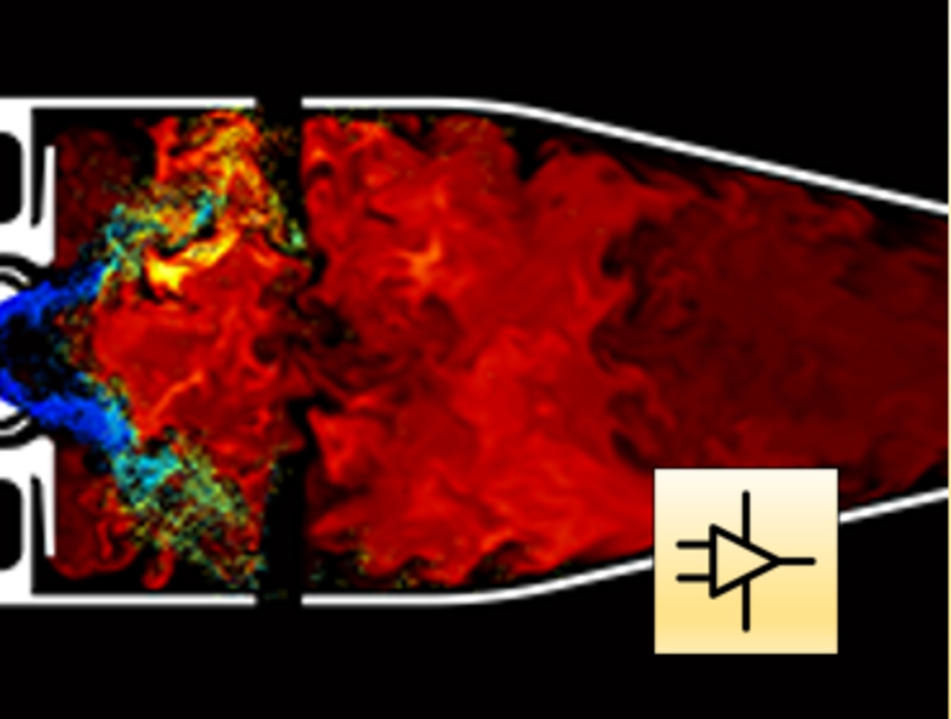
The technology is part of a new generation of NASA Glenn SiC integrated circuits with unprecedented durability in the field of high-temperature electronics. For robust operational amplifiers based on SiC Junction Field Effect Transistors (JFETs), this novel compensation method mitigates issues with threshold voltage variations that are an effect of die location on the wafer. Modern high-temperature op amps on the market fall short due to temperature limits (only 225C for silicon-based devices). Previously, researchers noted that multiple op amps on a single SiC wafer had different amplification properties due to different threshold voltages that varied spatially as much as 18% depending on the circuit's distance from the SiC wafer center. While 18% is okay for some applications, other important system applications demand better precision. By applying this technology to the amplifier circuit design process, the op amp will provide the same signal gain no matter its position on the wafer. The compensation approach enables practical signal conditioning that works from 25C up to 500C.
Electrical and Electronics

Coil-On-Plug Igniter for Reliable Engine Starts
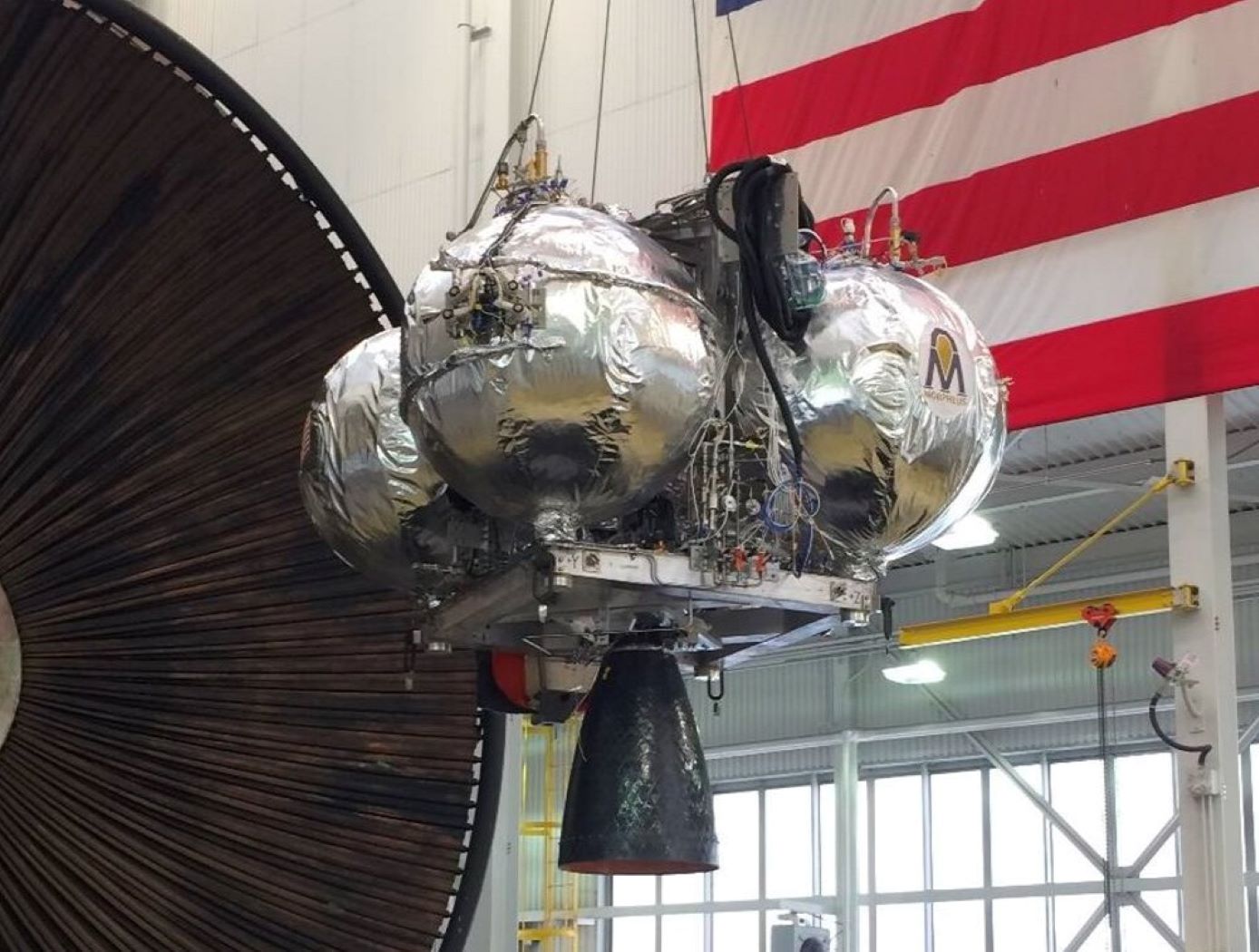
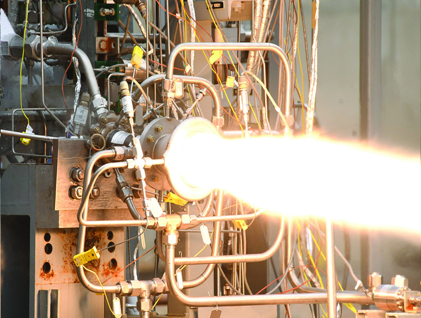
Spark-ignition devices have proven to be a high-reliability option for LOX/LCH4 ignition during development of the Integrated Cryogenic Propulsion Test Article (ICPTA) main and reaction control engines (RCEs); however, issues including spark plug durability (ceramic cracking) and corona discharge during simulated altitude testing have been observed, contributing to degraded spark output and no-light engine-start conditions. Innovators discovered that ignition system reliability could be improved and weight reduced by eliminating the traditional coil and spark plug wire. To achieve this result, engineers made the innovation by modifying an automotive coil-on-plug igniter to provide new high sparking energies at the point of combustion using low supply voltages. The coil was modified by vacuum-potting it into a threaded interface that mounts into existing spark plug ports on the ICPTA main engine and the RCEs. Engineers fabricated custom electrode tips that were thread-mounted into the potted coil body. Epoxy insulation was chosen with high dielectric strength to maintain insulation between the electrode and threaded adapter. Vacuum potting successfully prevented pressure or vacuum leakage into the coil body and maintained spark energy and location at the electrode tip. Successful hot-fire ignition was observed at sea-level, altitude, and thermal-vacuum for both ICPTA RCE and main engine igniters down to 10^-3 torr, which approaches the vacuum of cislunar space.
This technology is at technology readiness level (TRL) 7 (system prototype demonstration in an operational environment), and the related patent is now available to license. Please note that NASA does not manufacture products itself for commercial sale.
Sensors

Thin Film Sensor for Ultra High-Temp Measurement
The thin film sensor’s principal advantage lies in its potential to take high frequency temperature measurements from the surface of a reentering spacecraft while simultaneously withstanding the high temperature and oxidizing environment encountered. This data provides engineers with operational phase measurements used to refine the spacecraft’s operational envelope and track flight hardware behavior in addition to providing high frequency temperature measurements that can inform the physics of a boundary layer.
Mismatches in coefficients of thermal expansion (CTE) are expected in TPS-based sensor applications because the metallic materials used for temperature sensing have thermal expansion rates that differ from the rates of the substrate and coating materials in the TPS. At high temperatures during reentry, this mismatch in CTE can create a significant strain differential between the metallic sensor, sensor leads, and the materials to which the sensor and leads are bonded.
High frequency response temperature measurements on the surface of entry spacecraft are not currently possible above ~700 F with existing measurement capabilities. This shortcoming is primarily due to the need for robust sensor behavior at temperatures of several thousand degrees F. The sensor design of this technology preserves the integrity of sensor components while enhancing its high temperature functionality.
The thin film temperature sensor has a technology readiness level (TRL) 5 (Component and/or breadboard validation in relevant environment) and is now available for patent licensing. Please note that NASA does not manufacture products itself for commercial sale.
propulsion

A One-piece Liquid Rocket Thrust Chamber Assembly
The one-piece multi-metallic composite overwrap thrust chamber assembly is centrally composed of an additively manufactured integral-channeled copper combustion chamber. The central chamber is being manufactured using a GRCop42 or GRCop84 copper-alloy additive manufacturing technology previously developed by NASA. A bimetallic joint (interface) is then built onto the nozzle end of the chamber using bimetallic additive manufacturing techniques. The result is a strong bond between the chamber and the interface with proper diffusion at the nozzle end of the copper-alloy. The bimetallic interface serves as the foundation of a freeform regen nozzle. A blown powder-based directed energy deposition process (DED) is used to build the regen nozzle with integral channels for coolant flow. The coolant circuits are closed with an integral manifold added using a radial cladding operation. To complete the TCA, the entire assembly including the combustion chamber and regen nozzle is wrapped with a composite overwrap capable of sustaining the required pressure and temperature loads.


