Search
instrumentation

Damage Simulation Tool For Composite Laminates
The simulation combines existing fracture mechanics based damage propagation techniques with a discrete approach to modeling discontinuities in finite elements. Additionally, the use of an advanced laminate theory recovers deformation and stress information that would normally require a high fidelity model.
To accomplish this, the same theoretic and analytical concepts that a high fidelity numerical simulation tool utilizes for laminate damage simulation are placed in the context of a low fidelity finite element. In taking this approach, a laminate can be modeled as a single layer low fidelity shell mesh that has the ability to locally increase fidelity and represent a delamination based damage process but only if it is determined that one should occur.
The numerical simulation tool's performance has been validated against numerical benchmarks as well as experimental data.
Information Technology and Software
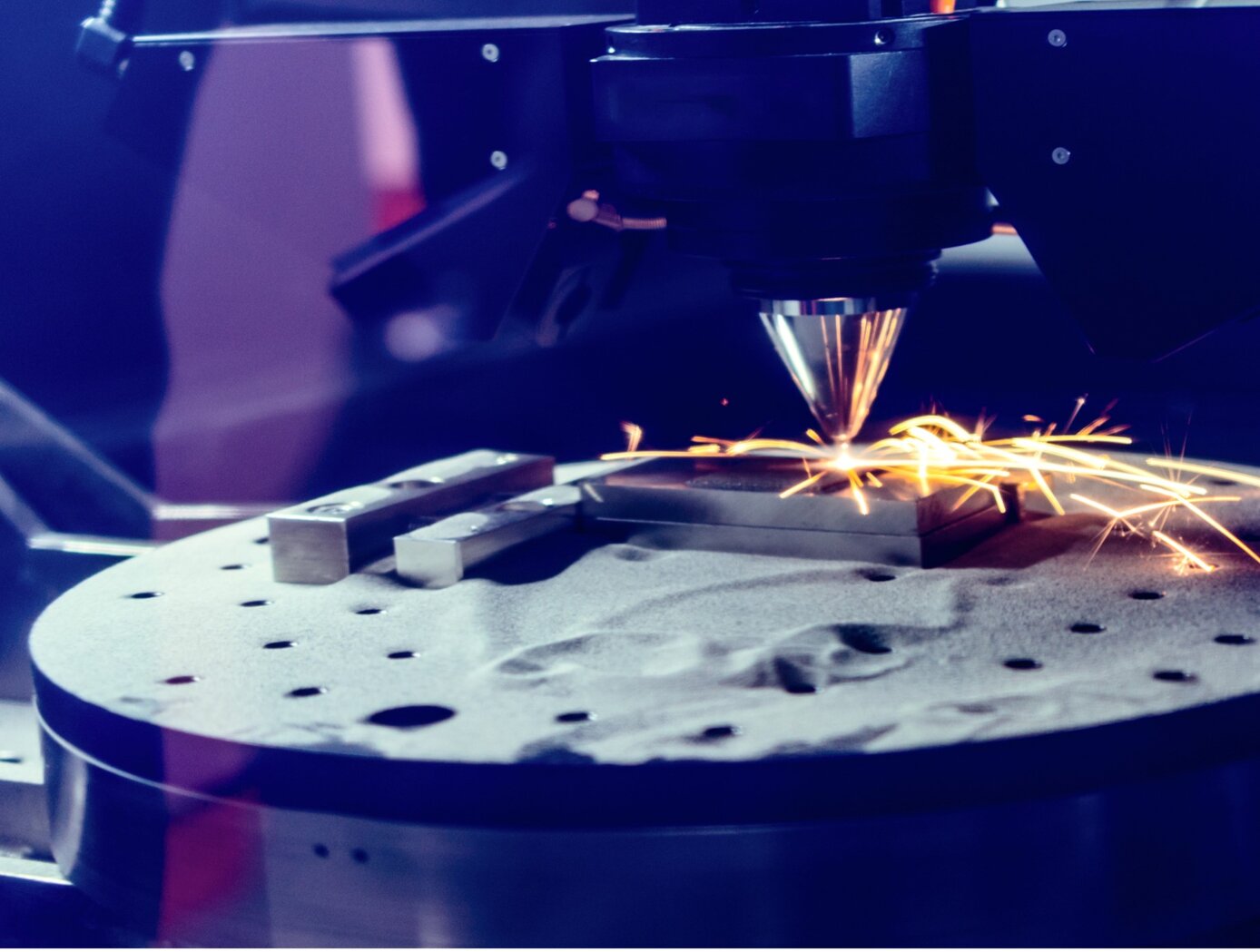
Additive Manufacturing Model-based Process Metrics (AM-PM)
Modeling additive manufacturing processes can be difficult due to the scale difference between the active processing point (e.g., a sub-millimeter melt pool) and the part itself. Typically, the tools used to model these processes are either too computationally intensive (due to high physical fidelity or inefficient computations) or are focused solely on either the microscale (e.g., microstructure) or macroscale (e.g., cracks). These pitfalls make the tools unsuitable for fast and efficient evaluations of additive manufacturing build files and parts.
Failures in parts made by laser powder bed fusion (L-PBF) often come when there is a lack of fusion or overheating of the metal powder that causes areas of high porosity. AM-PM uses a point field-based method to model L-PBF process conditions from either the build instructions (pre-build) or in situ measurements (during the build). The AM-PM modeling technique has been tested in several builds including a Ti-6Al-4V test article that was divided into 16 parts, each with different build conditions. With AM-PM, calculations are performed faster than similar methods and the technique can be generalized to other additive manufacturing processes.
The AM-PM method is at technology readiness level (TRL) 6 (system/subsystem model or prototype demonstration in a relevant environment) and is available for patent licensing.
materials and coatings

Computer-implemented energy depletion radiation shielding
The difference between Layered Energy Depletion Radiation Shielding (LEDRS) and Stacked Energy Depletion Radiation Shielding (SEDRS) is how the piece of matter, or shield, is analyzed as radiation passes through the matter.
SEDRS involves using a defined and ordered stack of layers of shielding with different material properties such that the thickness and chemical properties of each material maximizes the absorption of energy from the radiation particles that are most damaging to the target. The SEDRS shielding method aims to provide the maximum level of energy absorption while still keeping shielding mass and volume low.
The process of LEDRS involves using layers of shielding material such that the thickness of each material is designed to absorb the maximum amount of energy from the radiation particles that are most damaging to the target after subsequent layers of shielding. The more energy is absorbed by the shielding material, the less energy will be deposited in the target minimizing the required mass to achieve a resulting lower dose for a given geometrical feature. The LEDRS shielding method aims to provide the maximum level of energy absorption. The process for designing LEDRS views potential radiation shields as a cascade of effects from each shielding layer to the next and is helpful for investigating the particular effects of each layer.
SEDRS and LEDRS can improve any technology that relies on the controlled manipulation of a radiation field by interaction with a material element.
aerospace

Vertiport Assessment and Mobility Operations System (VAMOS!)
The term Advanced Air Mobility (AAM) refers to a new mode of transportation utilizing highly automated airborne vehicles for transporting goods and/or people. The adoption of widespread use of AAM vehicles will necessitate a network of vertiports located throughout a geographical region. A vertiport refers to a physical structure for the departure, arrival, and parking/storage of AAM vehicles. NASA-developed Vertiport Assessment and Mobility Operations System (VAMOS!) enables identifying geographical locations suitable for locating a vertiport or assessing suitability of pre-selected locations. For example, suitability evaluation factors include zoning, land use, transit stations, fire stations, noise, and time-varying factors like congestion and demand.
The vertiport assessment system assigns suitability values to these factors based on user-input, and types, including location-based (e.g., proximity to mass transit stations), level-based (e.g., noise levels), characteristic-based (e.g., residential zoning), and time-based (e.g., demand). Based on user input, the system spreads a grid over the geographical area, specifies importance criteria and weights for scaling the impact of the suitability factors, and identifies specific sub-regions as candidate locations. The candidate sub-regions are shown on a user interface map overlay in a color-coded gradient that reflects the suitability strength for a sub-region. Vertiport locations are selected within these sub-regions. These candidate vertiport locations are refined by establishing feasibility of flight between them. VAMOS! includes a modeling component and a simulation component. The modeling component assists a user to identify one or more geographical locations at which a vertiport may be physically built. The simulation component of the technology displays, in real-time, the simulated operational behavior of AAM vehicles and in the context of their projected flight paths combined with data dynamically obtained from live sources. These data sources can be from the Federal Aviation Administration (FAA) or other private or public governing bodies, from one or more AAM vehicles in flight, and from weather sources.
Aerospace

Aerodynamic Framework for Parachute Deployment from Aerial Vehicle
For rapid parachute deployment simulation, the framework and methodology provided by the simulation database uses parametrized aerodynamic data for a variety of environmental conditions, air taxi design parameters, and landing system designs. The database also includes a compilation of drag coefficients, thrust and lift forces, and further relevant aerodynamic parameters utilized in the simulated flight of a proposed air taxi. The database and framework can be constructed using simulated data that accounts for oscillatory breathing of parachutes. The methodology can further employ an overset grid of body-fitted meshes to accurately capture deployment of an internally-stored parachute, as well as descent of the air taxi and deployed parachute.
The systems and methods of the disclosed technology can be utilized with existing CFD solvers in a plug-and-play manner, such that the framework can be integrated to directly improve the performance of these solvers and the machines on which they are installed. The framework itself can employ parallelization to enable distributed solution of intensive CFD simulations to build a robust database of simulated data. Further, as up to 90% of computational time is spent in the calculation of aerodynamic parameters for use in coupled trajectory equations, the framework can significantly reduce the computational costs and design time for safe landing systems for air taxis. These reductions can lead to lower costs for design processes, while enabling rapid design and testing prior to physical prototyping.

