Search
Electrical and Electronics

Passive PCB-Mounted Thermal Switch
NASA’s Passive PCB-Mounted Thermal Switch uses a heat pipe that extends from the electronics enclosure wall to the center of the electronics board. The switch includes a wax actuator that extends when warm. The extending piston on the actuator pushes the heat pipe against the anvil of the mechanism, which then provides a low-resistance heat path to the wall of the enclosure. When the wax actuator drops below a certain temperature, the piston retracts. A spring then pushes the heat pipe away from the anvil, breaking thermal contact and conserving heat. A series of insulating materials is used to reduce unwanted heat transfer through the springs. The mechanism is mounted to the board with a thermal interface material and screws to provide high contact pressure and thermal conductivity between the board and the mechanism. Additional heat straps are used to carry heat directly from particularly hot components.
A key advantage of this NASA invention is that it does not require any energy input for operations (i.e., it is completely passive). In spaceflight applications, this enables significant mass savings as heaters can represent up to 50% of electronics systems’ power consumption. Given that typical battery chemistries stop functioning at approximately 0C, additional power is required to keep the batteries themselves warm. Thus, reducing heater power requirements by 50% could reduce overall energy storage requirements by approximately 70% – leaving more capacity for sensors, fuel, or other priorities.
NASA’s switch is particularly useful for spaceflight applications where electronics are exposed to long bouts of extreme heat and cold, such as on the Moon (where the day-night cycle lasts 14 days with nighttime lows near -173C and daytime highs near 127C), or in deep space. Lunar landers and lunar infrastructure developers might be ideal end-users of the invention. Other applications where electronics experience extreme temperatures may benefit from this NASA innovation.
materials and coatings
Aerofoam
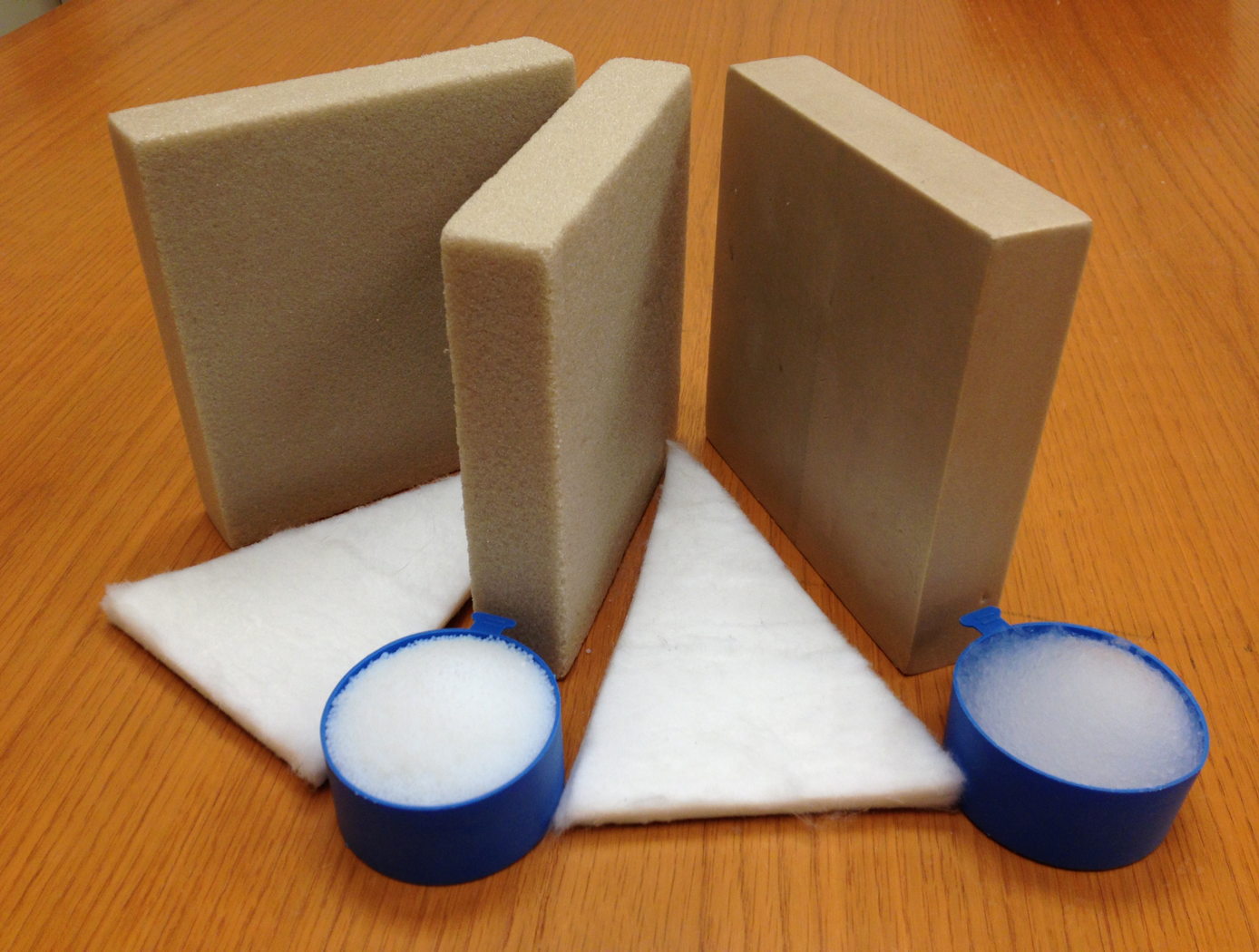
The Aerofoam composites have superior thermal and acoustic insulation properties when compared to conventional polyimide foams. In addition, they provide greater structural integrity than the fragile aerogel materials can provide independently. In general, polymer foams can provide excellent thermal insulation, and polyimide foams have the additional advantage of excellent high-temperature behavior and flame resistance compared to other polymer systems (they do not burn or release noxious chemicals). Incorporating aerogel material into the polyimide foam as described by this technology creates a composite that has been demonstrated to provide additional performance gains, including 25% lower thermal conductivity with no compromise of the structural integrity and high-temperature behavior of the base polyimide foam. The structural properties of Aerofoam are variable based on its
formulation, and it can be used in numerous rigid and flexible foams of varying densities.
Aerofoam has a number of potential commercial applications, including construction, consumer appliances, transportation, electronics, healthcare, and industrial equipment. In addition, these high-performance materials may prove useful in applications that require insulation that can withstand harsh environments, including process piping, tanks for transporting and storing hot or cold fluids, ship and boat building, and aerospace applications.
power generation and storage
High-Performance, Lightweight, Easy-to-Fabricate Heat Exchanger
Researchers at JPL have developed, built, and tested an innovative heat exchanger that offers reduced thermal expansion, increased structural strength, low pressure drop, and improved thermal performance while lowering the weight associated with typical heat exchangers. This innovation would benefit the commercial thermoelectric generator, aircraft, and industrial processing (i.e., glass, steel, petrochemical, cement, aluminum) industries by improving energy management/efficiency, reducing carbon dioxide emissions, and increasing system durability due to the reduced stress from thermal expansion.
<b>The Problem</b>
Thermoelectric generator systems require high-performance hot-side and cold-side heat exchangers to provide the temperature differential needed to transfer thermal energy while withstanding temperatures up to 650 °C. Because the hot-side heat exchangers must have a high heat flux, they are often made of metals such as stainless steel or Inconel<sup>®</sup> alloys. Although these materials can operate at high temperatures, resist corrosion, and are chemically stable, they also have several drawbacks: (1) Their lower thermal conductivity negatively affects their thermal performance. (2) Their higher thermal expansion leads to stresses that compromise system structural integrity. (3) Their high mass/volume reduces the power density of generator systems into which they are integrated. As a result, they are difficult to integrate into viable energy recovery systems. They also make the systems unreliable, non-durable, and susceptible to failures caused by thermal-structural expansion.
<b>The Solution</b>
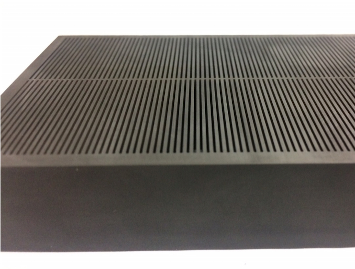
JPL researchers chose to replace the metal in traditional heat exchangers with graphite, which offers an improved conductivity-to-density ratio in thermal applications as well as a low coefficient of thermal expansion. In addition, they used a mini-channel design to further increase thermal performance. Combining more advanced materials with the innovative thermal design has yielded significant improvements in performance. For example, a 200-cm<sup>3</sup>, 128-g version of JPL's exchanger successfully transported 1,100 W from exhaust at nearly 550 °C with approximately 20 W/cm<sup>2</sup> thermal flux and a pressure drop of only 0.066 psi.
JPL's technology combines lightweight, high-strength graphite material with a mini-channel design that offers high thermal performance. Further development and testing are underway.
<em>Inconel is a registered trademark of Special Materials Corporation.</em>
manufacturing
Woven Thermal Protection System
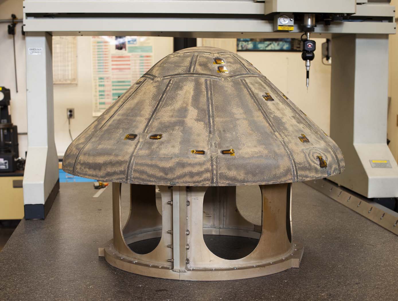
Going farther, faster and hotter in space means innovating how NASA constructs the materials used for heat shields. For HEEET, this results in the use of dual-layer, three-dimensional, woven materials capable of reducing entry loads and lowering the mass of heat shields by up to 40%. The outer layer, exposed to a harsh environment during atmospheric entry, consists of a fine, dense weave using carbon yarns. The inner layer is a low-density, thermally insulating weave consisting of a special yarn that blends together carbon and flame-resistant phenolic materials. Heat shield designers can adjust the thickness of the inner layer to keep temperatures low enough to protect against the extreme heat of entering an atmosphere, allowing the heat shield to be bonded onto the structure of the spacecraft itself. The outer and inner layers are woven together in three dimensions, mechanically interlocking them so they cannot come apart. To create this material, manufacturers employ a 3-D weaving process that is similar to that used to weave a 2-D cloth or a rug. For HEEET, computer-controlled looms precisely place the yarns to make this kind of complex three-dimensional weave possible. The materials are woven into flat panels that are formed to fit the shape of the capsule forebody. Then the panels are infused with a low-density version of phenolic material that holds the yarns together and fills the space between them in the weave, resulting in a sturdy final structure. As the size of each finished piece of HEEET material is limited by the size of the loom used to weave the material, the HEEET heat shield is made out of a series of tiles. At the points where each tile connects, the gaps are filled through inventive designs to bond the tiles together.
materials and coatings
Conductive Carbon Fiber Polymer Composite
The new composite developed by NASA incorporates PGS and CNTs to enhance its thermal conductivity while preserving the mechanical properties of the underlying carbon fiber polymer composite. NASA has also improved the composite manufacturing process to ensure better thermal conductivity not only on the surface, but also through the thickness of the material. This was achieved by adding perforations that enable the additives to spread through the composite.
The process for developing this innovative, highly thermally conductive hybrid carbon fiber polymer composite involves several steps. Firstly, a CNT-doped polymer resin is prepared to improve the matrix's thermal conductivity, which is then infused into a carbon fiber fabric. Secondly, PGS is treated to enhance its mechanical interface with the composite. Thirdly, perforation is done on the pyrolytic graphite sheet to improve the thermal conductivity through the thickness of the material by allowing CNT-doped resin to flow and better interlaminar mechanical strength. Finally, the layup of PGS and CNT-CF polymer is optimized.
Initial testing of the composite has shown significant increases in thermal conductivity compared to typical carbon fiber composites, with a more than tenfold increase. The composite also has higher thermal conductivity than aluminum alloys, with more than twice the thermal conductivity of the Aluminum 6061 typically used in the aerospace industry. For this new material, NASA has completed a proof-of-concept demonstration and work continues to use the material in a heat exchanger system and further characterize the properties including longevity and radiation impact analysis.
Materials and Coatings

Advanced Materials for Electronics Insulation
Many researchers have attempted to use polymer-ceramic composites to improve the thermal and dielectric performance of polymer insulation for high voltage, high temperature electronics. However, using composite materials has been challenging due to manufacturing issues like incomplete mixing, inhomogeneous properties, and void formation. Here, NASA has developed a method of preparing and extruding polymer-ceramic composites that results in high-quality, flexible composite ribbons.
To achieve this, pellets of a thermoplastic (e.g., polyphenylsulfone or PPSU) are coated with an additive then mixed with particles of a ceramic (e.g., boron nitride or BN) as shown in the image below. After mixing the coated polymer with the ceramic particles, the blended material was processed into ribbons or films by twin-screw extrusion. The resulting ribbons are highly flexible, well-mixed, and void free, enabled by the coated additive and by using a particle mixture of micronized BN and nanoparticles of hexagonal BN (hBN).
The polymer-ceramic composite showed tunable dielectric and thermal properties depending on the exact processing method and composite makeup. Compared to the base polymer material, the composite ribbons showed comparable or improved dielectric properties and enhanced thermal conductivity, allowing the composite to be used as electrical insulation in high-power, high-temperature conditions.
The related patent is now available to license. Please note that NASA does not manufacturer products itself for commercial sale.
Optics

Thermally-Adaptive Solid State Laser Crystal Mount
NASA’s laser mount technology introduces a unique flexible crystal mount to accommodate the dynamics of thermal expansion to eliminate unsymmetrical thermally induced mechanical stresses on the crystal. In addition, while the mount accommodates thermal expansion, it also offers fixed placement of the crystal to maintain alignment and provides continuous and uniform surface contact between the mount and crystal for rapid dissipation of heat. The mount is compatible with any heat sink reservoir.
The mount design allows unrestrained thermal expansion of the crystal in two dimensions (i.e. a- and c- axes) because of the design shown in the figure below.
The L-shape blocks also deliver cooling to the crystal by providing a path to the heat sink reservoir. The L-shape blocks are manufactured with a high thermal conductivity material such as copper. A softer material with high thermal conductivity such as indium is used to buffer the interface between the crystal and the L-shape blocks surfaces. A coolant medium acts to transfer the heat from the crystal to the cooled mount. Cooling can be provided in different ways – for example by water or by heat pipes with radiator (for use in space). The springs used to hold the laser crystal also provide the adjustment method to align the beam, and once aligned, the crystal mount is very stable.
The related patent is now available to license. Please note that NASA does not manufacture products itself for commercial sale.
Materials and Coatings

Non-Magnetic Absorptive Material for Microwave to Far-Infrared Applications
The electromagnetic properties of the material are engineered by optimizing its complex dielectric function through the volume filling fraction of its components. A low-index polymeric binder, such as thermal polymers and epoxies, serves as the host medium to minimize reflectance in the conductively loaded dielectric media. To ensure thermal compatibility with metal substrates in cryogenic environments, dielectric powders are incorporated to match thermal expansion. Additionally, alumina frit compensates for thermal contraction at cryogenic temperatures, while non-magnetic conductive particles such as bronze, carbon allotropes, and degenerately doped silicon help tailor the material’s dielectric response.
To enhance performance, small-particle scatterers reduce heat capacity and limit resonant dispersion, while dirty alloys stabilize resistance under conductive loading. The formulation incorporates reststrahlen materials and supports applications across the microwave to terahertz range, making it suitable for baffles, Lyot stops, and optical terminations, or as a primer for enhancing near-infrared and visible black paints.
This high-emissivity, non-magnetic coating is designed for microwave to far-infrared instrumentation in space and cryogenic systems. It also benefits industries producing absorptive epoxies, EMI/EMC shielding, and quantum sensing components. It has reached Technology Readiness Level (TRL) 5 (component validation in relevant environment) and is now available for patent licensing.
Optics
Fingerprinting for Rapid Battery Inspection
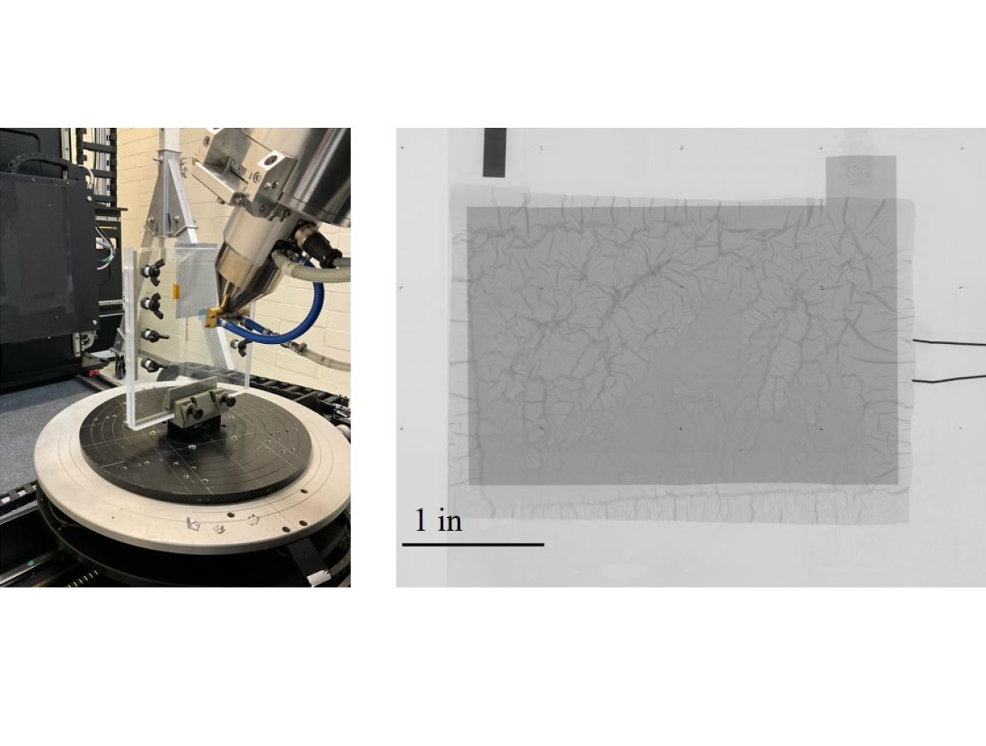
The technology utilizes photopolymer droplets (invisible to the digital radiograph) with embedded radiopaque fragments to create randomized fingerprints on battery samples. The droplets are deposited using a jig (see figure on right) that precisely positions samples. Then, at different points during battery R&D testing or use, digital radiography imaging with micron-level resolution can be performed.
The high-resolution imaging required to detect dendrite formation requires images to be collected in multiple “tiles” as shown below. The randomized fingerprints uniquely identify relative positioning of these tiles, allowing rapid assembly of composite high-resolution images from multiple tiles.
This same composite creation process can be used for images taken at a series of points in time during testing, and background subtraction can be applied to efficiently compare how the battery is changing over successive charge/discharge cycles to identify dendrite formation. This inspection technique is proven effective for thin-film pouch cell prototypes at NASA, and it works well at the lowest available x-ray energy level (limiting impact on the samples). The Fingerprinting for Rapid Battery Inspection technology is available for patent licensing.
Materials and Coatings

New Methods in Preparing and Purifying Nanomaterials
Sometimes called white graphite, affordable and plentiful hBN possesses the same kind of layered molecular structure as graphite. In graphite, this structure has allowed next-generation nanomaterials like carbon nanotubes and graphene to be produced. With hBN, however, the process of converting the substance into boron nitride nanotubes (BNNT) has been too difficult to yield commercial quantities. Glenn innovators have created several new methods that could enable greater adoption of this unique nanomaterial. In the initial stage, the starter reactant is mixed with a selected set of chemicals (a metal chloride, for example) and an activation agent (such as sodium fluoride). This mixture causes hBN to become less resistant to intercalation. The intercalated product can then be exfoliated by heating the material in air, and giving the material a final rinse with a liquid-phase ferric chloride salt to dissolve any embedded impurities without damaging its internal structure. These efficiently exfoliated nanomaterials can be used to form advanced composite materials (e.g., layered with aluminum oxide to form hBN/alumina ceramic composites). Nanomaterials fabricated from hBN can also take advantage of the material's unique combination of being an electrical insulator with high thermal conductivity for applications ranging from microelectronics to energy harvesting. Glenn's innovations have enabled a significantly improved matrix composite material with the potential to make a significant impact on the commercial materials market.

