Assembly for Simplified Hi-Res Flow Visualization
instrumentation
Assembly for Simplified Hi-Res Flow Visualization (LAR-TOPS-348)
Self-aligned, single grid projection focusing schlieren imaging system
Overview
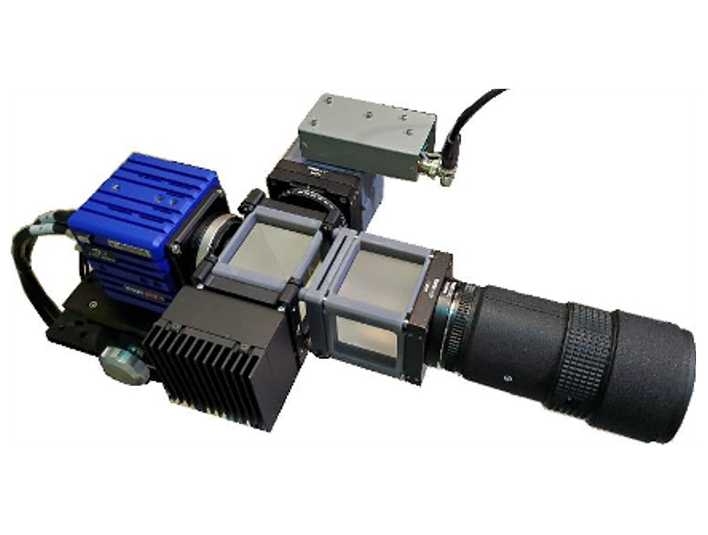
Researchers at NASAs Langley Research Center have developed a simple, compact, easy-to-use projection focusing schlieren imaging system optical assembly that leverages a light source, a single physical grid element, and polarization optics to enable hi-res flow visualization. The assembly can simply be mounted in front of a camera to enable focusing schlieren imaging capability. The assembly was designed to drastically reduce the complexity and time required to align a focusing schlieren imaging experiment.
Conventional focusing schlieren imaging systems and projection-based analogs require cumbersome grid alignment and peripheral resources to function (e.g., separate source and cutoff grids, projectors, specialized software). NASAs system leverages a single physical grid as both the source and cutoff grid, so the system is self-aligned, compact, does not require specialized software, and costs less than other projection-based alternatives.
The Technology
NASAs single grid, self-aligned focusing schlieren optical assembly is attached to a commercial-off-the-shelf camera. It directs light from the light source through a condenser lens and linear polarizer towards a polarizing beam-splitter where the linear, vertically-polarized component of light is reflected onto the optical axis of the instrument. The light passes through a Ronchi ruling grid, a polarizing prism, and a quarter-wave plate prior to projection from the assembly as right-circularly polarized light. The grid-patterned light (having passed through the Ronchi grid) is directed past the density object onto a retroreflective background that serves as the source grid. Upon reflection off the retroreflective background, the polarization state of light is mirrored. It passes the density object a second time and is then reimaged by the system. Upon encountering the polarizing prism the second time, the light is refracted resulting in a slight offset. This refracted light passes through the Ronchi ruling grid, now serving as the cutoff grid, for a second time before being imaged by the camera.
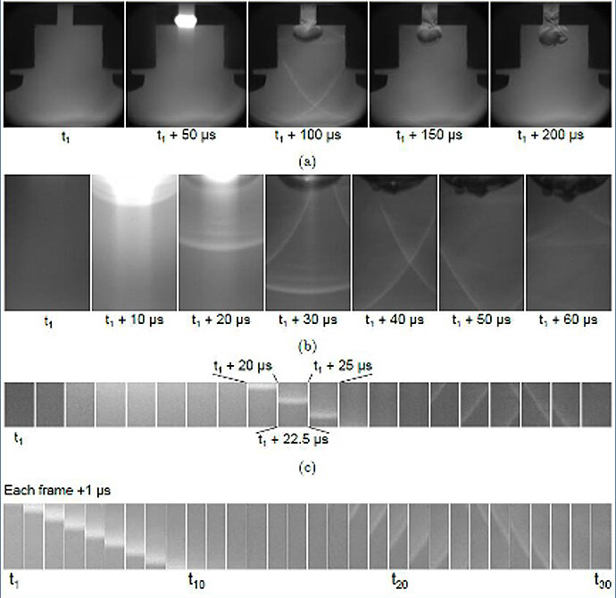
Both small- and large-scale experimental set ups have been evaluated and shown to be capable of fields-of-view of 10 and 300 millimeters respectively. Observed depths of field were found to be comparable to existing systems. Light sources, polarizing prisms, retroreflective materials and lenses can be customized to suit a particular experiment. For example, with a high speed camera and laser light source, the system has collected flow images at a rate of 1MHz.


Benefits
- Easy to use: The single grid design is inherently self-aligned (i.e., precludes the need for fabrication of a source-matched cutoff grid) and the sensitivity is easy to adjust which simplifies set-up saving time (i.e., hours to days) and expands potential user base to those outside of experts in optical diagnostics instrumentation.
- Compact: The optical assembly is small enough to be mounted like a lens in front of a camera enabling efficient use of space (or room for additional instruments) in cramped experimental environments such as wind tunnels.
- Vibration insensitive: The self-aligning nature of the instrument prevents grid misalignment issues common to currently employed focusing schlieren instruments
- High-speed imaging capable: Demonstrated framing rates up to 1 MHZ (dependent on camera and light source used)
- Modular: System components can be optimized for a given environment, experiment, or cost as the design and method is capable of employing a wide array of light sources, cameras, polarizing prisms, and retroreflective materials.
Applications
- Aerospace: Flow visualization, aerodynamics and fluid dynamics R&D
- Thermal Management: instrument to visualize or monitor heat transfer from sensitive electronic devices (e.g., to diagnose thermal issues or determine efficacy of thermal management solutions)
- Medical: Instrument for contamination control (e.g., mask efficacy, clean room air flows) and diagnostic imaging of air flows or fluid flows
- Manufacturing: Instrument to visualize gas flow or thermal flow imaging for additive manufacturing or semiconductor manufacturing processes
- Ventilation: Instrument to visualize air flow from ventilation systems
- Education: Instrument for primary, secondary, undergraduate or graduate laboratory experiments.
Technology Details
instrumentation
LAR-TOPS-348
LAR-19882-1
Compact, self-aligned focusing schlieren system (June 14, 2021) by inventors Brett F. Bathel and Joshua M. Weisberger in Optics Letters: https://doi.org/10.1364/OL.428011
Development of a Self-Aligned Compact Focusing Schlieren System for NASA Test Facilities (December 29, 2021) presentation at AIAA SCITECH 2022 Forum by inventors Brett F. Bathel and Joshua M. Weisberger: https://arc.aiaa.org/doi/abs/10.2514/6.2022-0560
|
Tags:
|
Similar Results

Digital Projection Focusing Schlieren System
NASAs digital projection focusing schlieren system is attached to a commercial-off-the-shelf camera. For focusing schlieren measurements, it directs light from the light source through a condenser lens and linear polarizer towards a beam-splitter where linear, vertically-polarized component of light is reflected onto the optical axis of the instrument. The light passes through the patterned LCD element, a polarizing prism, and a quarter-wave plate prior to projection from the assembly as left- or right-circularly polarized light. The grid-patterned light (having passed through the LCD element) is directed past the density object onto a retroreflective background (RBG) that serves as the source grid. Upon reflection off the RBG, the polarization state of light is mirrored. It passes the density object a second time and is then reimaged by the system. Upon encountering the polarizing prism the second time, the light is slightly offset. This refracted light passes through the LCD element, now serving as the cutoff grid, for a second time before being imaged by the camera.
The LCD element can be programmed to display a variety of grid patterns to enable sensitivity to different density gradients. the color properties of the LCD can be leveraged in combination with multiple colored light sources to enable simultaneous multi-color, multi-technique data collection.

Projected Background-Oriented Schlieren Imaging
The Projected BOS imaging system developed at the NASA Langley Research Center provides a significant advancement over other BOS flow visualization techniques. Specifically, the present BOS imaging method removes the need for a physically patterned retroreflective background within the flow of interest and is therefore insensitive to the changing conditions due to the flow. For example, in a wind tunnel used for aerodynamics testing, there are vibrations and temperature changes that can affect the entire tunnel and anything inside it. Any patterned background within the wind tunnel will be subject to these changing conditions and those effects must be accounted for in the post-processing of the BOS image. This post-processing is not necessary in the Projected BOS process here.
In the Projected BOS system, a pattern is projected onto a retroreflective background across the flow of interest (Figure 1). The imaged pattern in this configuration can be made physically (a pattern on a transparent slide) or can be digitally produced on an LCD screen. In this projection scheme, a reference image can be taken at the same time as the signal image, facilitating real-time BOS imaging and the pattern to be changed or optimized during the measurements. Thus far, the Projected BOS imaging technology has been proven to work by visualizing the air flow out of a compressed air canister taken with this new system (Figure 2).

Reflection-Reducing Imaging System for Machine Vision Applications
NASAs imaging system is comprised of a small CMOS camera fitted with a C-mount lens affixed to a 3D-printed mount. Light from the high-intensity LED is passed through a lens that both diffuses and collimates the LED output, and this light is coupled onto the cameras optical axis using a 50:50 beam-splitting prism.
Use of the collimating/diffusing lens to condition the LED output provides for an illumination source that is of similar diameter to the cameras imaging lens. This is the feature that reduces or eliminates shadows that would otherwise be projected onto the subject plane as a result of refractive index variations in the imaged volume. By coupling the light from the LED unit onto the cameras optical axis, reflections from windows which are often present in wind tunnel facilities to allow for direct views of a test section can be minimized or eliminated when the camera is placed at a small angle of incidence relative to the windows surface. This effect is demonstrated in the image on the bottom left of the page.
Eight imaging systems were fabricated and used for capturing background oriented schlieren (BOS) measurements of flow from a heat gun in the 11-by-11-foot test section of the NASA Ames Unitary Plan Wind Tunnel (see test setup on right). Two additional camera systems (not pictured) captured photogrammetry measurements.

Optical Head-Mounted Display System for Laser Safety Eyewear
The system combines laser goggles with an optical head-mounted display that displays a real-time video camera image of a laser beam. Users are able to visualize the laser beam while his/her eyes are protected. The system also allows for numerous additional features in the optical head mounted display such as digital zoom, overlays of additional information such as power meter data, Bluetooth wireless interface, digital overlays of beam location and others. The system is built on readily available components and can be used with existing laser eyewear. The software converts the color being observed to another color that transmits through the goggles. For example, if a red laser is being used and red-blocking glasses are worn, the software can convert red to blue, which is readily transmitted through the laser eyewear. Similarly, color video can be converted to black-and-white to transmit through the eyewear.

Fluid Lensing System for Imaging Underwater Environments
Fluid lensing exploits optofluidic lensing effects in two-fluid interfaces. When used in such interfaces, like air and water, coupled with computational imaging and a unique computer vision-processing pipeline, it not only removes strong optical distortions along the line of sight, but also significantly enhances the angular resolution and signal-to-noise ratio of an otherwise underpowered optical system. As high-frame-rate multi-spectral data are captured, fluid lensing software processes the data onboard and outputs a distortion-free 3D image of the benthic surface. This includes accounting for the way an object can look magnified or appear smaller than usual, depending on the shape of the wave passing over it, and for the increased brightness caused by caustics. By running complex calculations, the algorithm at the heart of fluid lensing technology is largely able to correct for these troublesome effects. The process introduces a fluid distortion characterization methodology, caustic bathymetry concepts, Fluid Lensing Lenslet Homography technique, and a 3D Airborne Fluid Lensing Algorithm as novel approaches for characterizing the aquatic surface wave field, modeling bathymetry using caustic phenomena, and robust high-resolution aquatic remote sensing. The formation of caustics by refractive lenslets is an important concept in the fluid lensing algorithm. The use of fluid lensing technology on drones is a novel means for 3D imaging of aquatic ecosystems from above the water's surface at the centimeter scale. Fluid lensing data are captured from low-altitude, cost-effective electric drones to achieve multi-spectral imagery and bathymetry models at the centimeter scale over regional areas. In addition, this breakthrough technology is developed for future in-space validation for remote sensing of shallow marine ecosystems from Low Earth Orbit (LEO). NASA's FluidCam instrument, developed for airborne and spaceborne remote sensing of aquatic systems, is a high-performance multi-spectral computational camera using Fluid lensing. The space-capable FluidCam instrument is robust and sturdy enough to collect data while mounted on an aircraft (including drones) over water.


